Fluid filled vibration damping device

a technology of vibration damping and flue gas, which is applied in the direction of shock absorbers, machine supports, mechanical equipment, etc., can solve the problems of reducing the vibration damping capability of the orifice passage, the risk of a drop in the vibration damping capability of the input vibration, and the cavitation noise and vibration. , to achieve the effect of shortening the passage length of the shunt hole, reducing or eliminating cavitation noise and vibration, and reducing the thickness of the orifice passag

Active Publication Date: 2013-06-04
SUMITOMO RIKO CO LTD +1
View PDF12 Cites 10 Cited by
  • Summary
  • Abstract
  • Description
  • Claims
  • Application Information

AI Technical Summary

Benefits of technology

[0012]It is therefore an object of the present invention to provide a fluid filled type vibration damping device of novel structure which, through a simple structure with a minimal number of parts, will effectively produce the desired vibration damping action during input of vibration to be damped; and that during input of large impulsive load will suppress pressure fluctuations within the pressure receiving chamber and reduce or eliminate noise and vibration attributed to negative pressure within the pressure receiving chamber.

Problems solved by technology

A problem with sealed fluid type vibration damping devices of this kind is that noise and vibration sometimes occur when an impulsive load is input across the first mounting member and the second mounting member.
Such noise and vibration are attributed to the phenomenon of cavitation due to negative pressure within the pressure receiving chamber in association with input of a large load.
Specifically, since problematic noise and vibration are created by a drop in pressure within the pressure receiving chamber, by providing a shunt hole through which the pressure receiving chamber and the equilibrium chamber communicate via a shorter passage length than the orifice passage, even in the event that flow of fluid through the orifice passage cannot keep up, fluid will nevertheless be transported from the pressure receiving chamber to the equilibrium chamber through the shunt hole.
However, in a fluid filled type vibration damping device provided with such a shunt hole, there is a risk of a drop in vibration damping capability during input of vibration to be damped.
Thus, there is a danger that sufficient flow of fluid through the orifice passage will not be achieved, resulting in an appreciable decline in the vibration damping capability of the orifice passage.
However, in a fluid filled vibration damping device of a structure equipped with a valve body, which is provided for opening and closing the shunt passage such as taught in US-2007 / 0075470A1, the durability of the valve body will tend to be a problem with repeated operation over an extended period.
Furthermore, in some instances, it is exceptionally difficult to tune the operation of the valve body in such a way that it can switch the shunt passage between the communicating state and the blocked state with a high degree of accuracy in response to input of specific vibration.
Also, where a special valve body is provided, the problems of an increased number of parts and more complex structure may result.

Method used


Image

  • Fluid filled vibration damping device
  • Fluid filled vibration damping device
  • Fluid filled vibration damping device

Examples


Embodiment Construction

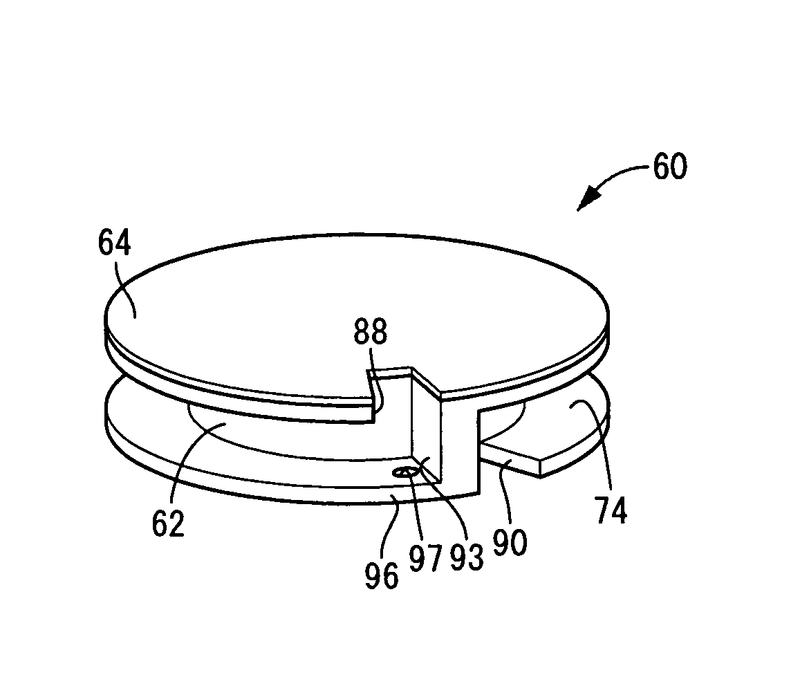
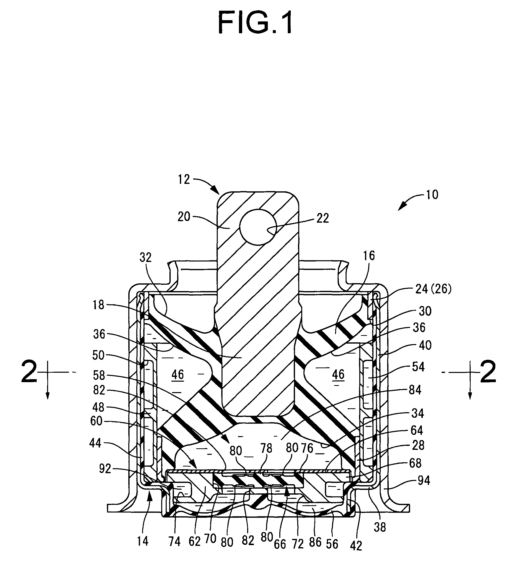
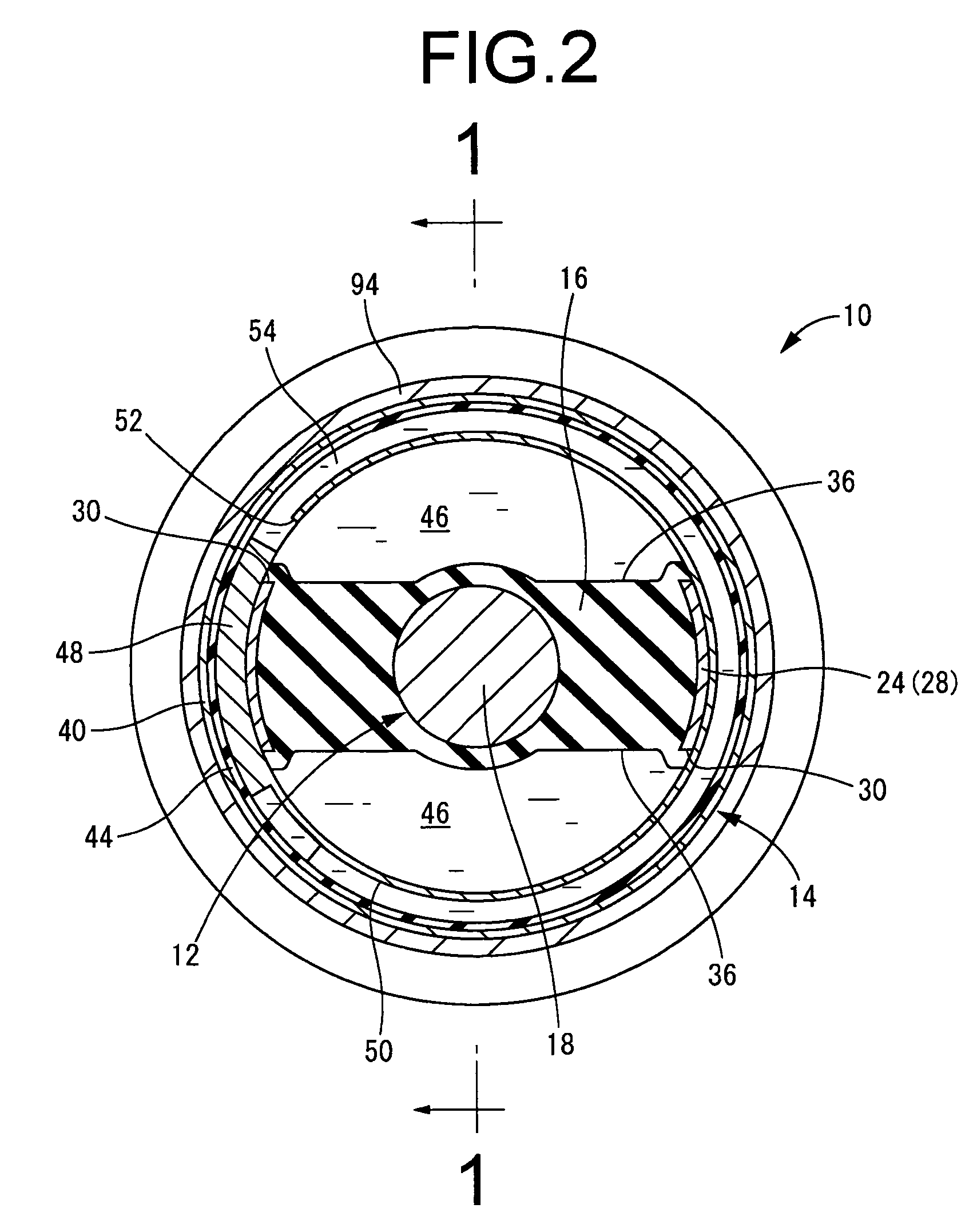
[0049]First, FIG. 1 and FIG. 2 depict an automotive engine mount 10 according to a first embodiment of a fluid filled type vibration damping device of the present invention. This automotive engine mount 10 has a structure in which a first mounting member 12 of metal is situated in proximity to and spaced apart from the opening at the axial upper end of a second mounting member 14 of metal, with the first and second mounting members 12, 14 elastically connected together by a main rubber elastic body 16. In the description herein, the vertical direction shall as general rule refer to the vertical direction in FIG. 1, which is also the axial direction of the second mounting member 14.

[0050]To describe in greater detail, the first mounting member 12 has solid, small-diameter rod contours extending in a straight line, and is fabricated of high rigidity material such as iron or aluminum alloy. The first mounting member 12 has a structure with an integrally formed mounting portion 20 of ta...


PUM


Abstract

A fluid filled vibration damping device having an orifice passage formed in a partition member to connect a pressure receiving chamber and an equilibrium chamber, wherein a first end section of the orifice passage extends in along a plane of the partition member, and a communication hole is formed to bend at a right angle from the first end of the orifice passage and open towards the pressure receiving chamber to form a dead water region by orthogonal wall faces of a terminal end face and a bottom face of the orifice passage in a connecting corner section of the orifice passage with the communication hole. A shunt hole of smaller cross-sectional area than the orifice passage and the communication hole is formed in a bottom wall so that the pressure receiving chamber and the equilibrium chamber communicate through the shunt hole in the dead water region.

Description

INCORPORATED BY REFERENCE[0001]The disclosure of Japanese Patent Application No. 2007-210139 filed on Aug. 10, 2007 including the specification, drawings and abstract is incorporated herein by reference in its entirety.BACKGROUND OF THE INVENTION[0002]1. Field of the Invention[0003]The present invention relates to a vibration damping device adapted for installation between components which make up a vibration transmission system, to provide vibration-damped coupling and / or vibration-damped support between the components making up the vibration transmission system; and relates in particular to a fluid filled type vibration damping device which utilizes vibration damping action based on the flow effect of a non-compressible fluid filling the interior.[0004]2. Description of the Related Art[0005]There are a number of vibration damping devices known in the art for the purpose of installation between vibration-damped components, such as the power unit and the vehicle body of an automobil...

Claims


Application Information

Patent Timeline
Patent Type & Authority Patents(United States)
IPC IPC(8): F16F5/00F16F9/00
CPCF16F13/107
Inventor NISHI, NAOKIMIYAHARA, TETSUYA
Owner SUMITOMO RIKO CO LTD
Why Eureka
Try Eureka