
Waterproof assembly for electronic device and watertight door thereof

a technology of electronic devices and components, applied in the direction of electrical apparatus casings/cabinets/drawers, furniture parts, instruments, etc., can solve the problems of short circuit, failure of waterproofing implementation, further damage to electronic devices, etc., and achieve the effect of avoiding damag

Active Publication Date: 2013-06-04
GETAC TECH CORP
View PDF44 Cites 41 Cited by
  • Summary
  • Abstract
  • Description
  • Claims
  • Application Information

AI Technical Summary

Benefits of technology

[0012]To achieve the aforementioned problems, a waterproof assembly of the present invention is introduced, which has long life span and provides well waterproofing effect.
[0014]The water absorbing ring expands after absorbing the water. Therefore, the water absorbing ring would not easily be damage when placing the cover into the opening, so as to maintain waterproofing effect of the water absorbing ring.

Problems solved by technology

A portable electronic device for being operated outdoor, such as a rugged laptop computer, is often sprayed by water occasionally under adverse circumstances.
However, the above waterproofing implementation is semi-permanent, and the waterproofing implementation will failed when the case is dismounted.
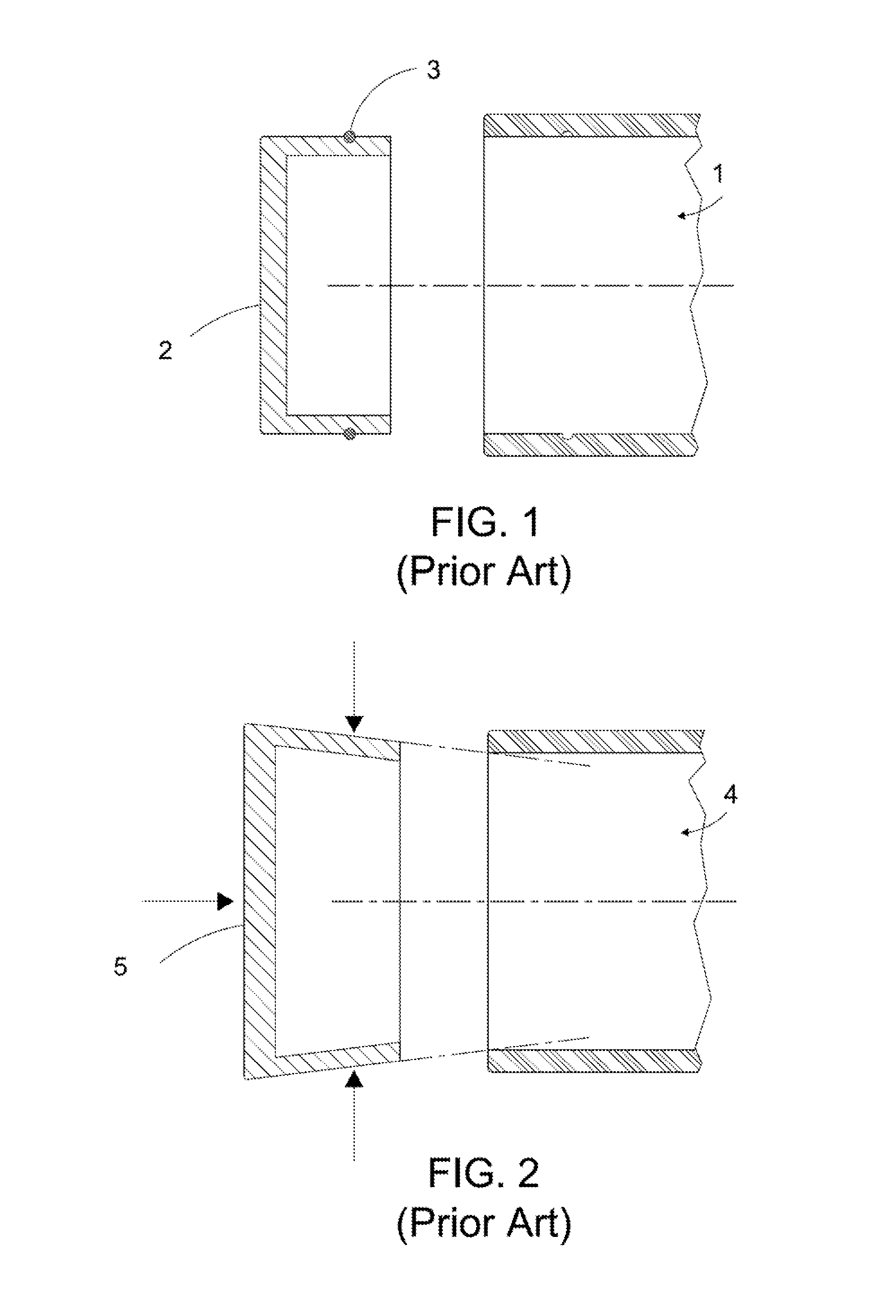
In FIGS. 1 and 2, when the cover bodies 2 and 5 are not properly mounted (for example, the cover bodies are not mounted on correct positions), or the element made of an elastic material is broken, the water still runs through the gaps between the cover bodies 2 and 5 and the openings 1 and 4, so as to directly result in a short circuit of the electrical connectors or the sockets, and further damage the electronic device when water enters the case.
However, if a large contact pressure is provided, the difficulty for mounting and dismounting the cover bodies 2 and 5 is increased, and the elastic sleeve ring 3 or the cover body 5 made of the elastic material is easily broken.
If the contact pressure is small, the waterproofing effect is distinctly poor.
Therefore, it becomes a technical problem how to modify the waterproofing measures on the electrical connection ports and corresponding openings when the rugged laptop computer and other portable electronic devices are fabricated.

Method used


Image

  • Waterproof assembly for electronic device and watertight door thereof
  • Waterproof assembly for electronic device and watertight door thereof
  • Waterproof assembly for electronic device and watertight door thereof

Examples


first embodiment

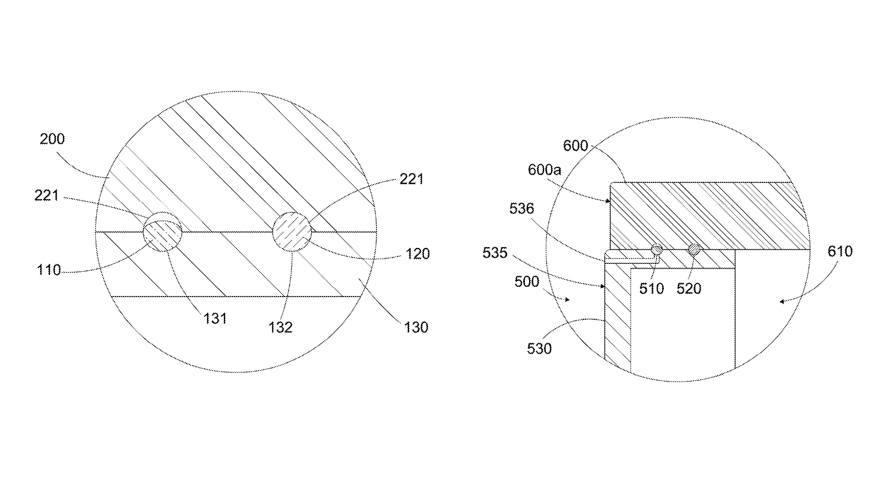
[0044]Referring to FIGS. 12 and 13, in the first embodiment, the first annular groove 221 and the second annular groove 222 may be omitted, and the water blocking ring 120 directly contacts the inner peripheral surface 220, and is normally compressed between the inner peripheral surface 220 and the outer peripheral surface 133, such that the water blocking ring 110 contacts the inner peripheral surface 220 in a surface contact manner. As shown in FIG. 12, before absorbing the water, the water absorbing ring 110 maintains not contacting the inner peripheral surface 220 or contacts the inner peripheral surface 220 at a low contact pressure. Referring to FIG. 13, when the water enters the gap between the cover 130 and the inner peripheral surface 220, the water absorbing ring 110 absorbs the water and expands, and meanwhile is compressed to be deformed, so as to contact the inner peripheral surface 220 in the surface contact manner.

[0045]In the embodiments of the present invention, the...

fourth embodiment

[0059]Referring to FIG. 20, a water absorbing ring 710 according to the present invention is shown. The water absorbing ring 710 is used in the watertight door according to one or more embodiments of the present invention. The water absorbing ring 710 includes an outer mantle layer 711 and a water absorbing layer 712.

[0060]The outer mantle layer 711 is made of deformable material, and has a plurality of slits 711b formed thereon. Each slits 710b partially cuts the outer mantle layer 511 along a radial direction of the water absorbing ring 710. A part of or all of the water absorbing layer 712 is made of a water absorbent, and the water absorbing layer 712 is wrapped by the outer mantle layer 711. Water runs through the outer mantle layer 711 through the slits 711b, and is absorbed by the water absorbing layer 712. The water absorbing layer 512 absorbs the water and expands, so as to press against the outer mantle layer 711 outwards, thereby increasing a cross-sectional area of the w...

fifth embodiment

[0062]Referring to FIG. 23, a water absorbing ring 810 according to the present invention is shown. The water absorbing ring 810 is used in the watertight door according to one or more embodiments of the present invention. The water absorbing ring 810 includes a water permeable layer 813 and a water absorbing layer 812.

[0063]The water permeable layer 813 is made of deformable material, and the water permeable layer 813 has a plurality of pores, so as to enable water to run through. The water permeable layer 813 is made of non-woven fabric or other fabric materials, which has characteristics of the deformable material, and has numerous tiny pores. A part of or the entire water absorbing layer 812 is made of a water absorbent. The water absorbing layer 812 is wrapped by the water permeable layer 813, and absorbs the water through the pores and expands. Since the material of the water permeable layer 813 is deformable, the water permeable layer 813 is deformed along with the water abso...


PUM


Abstract

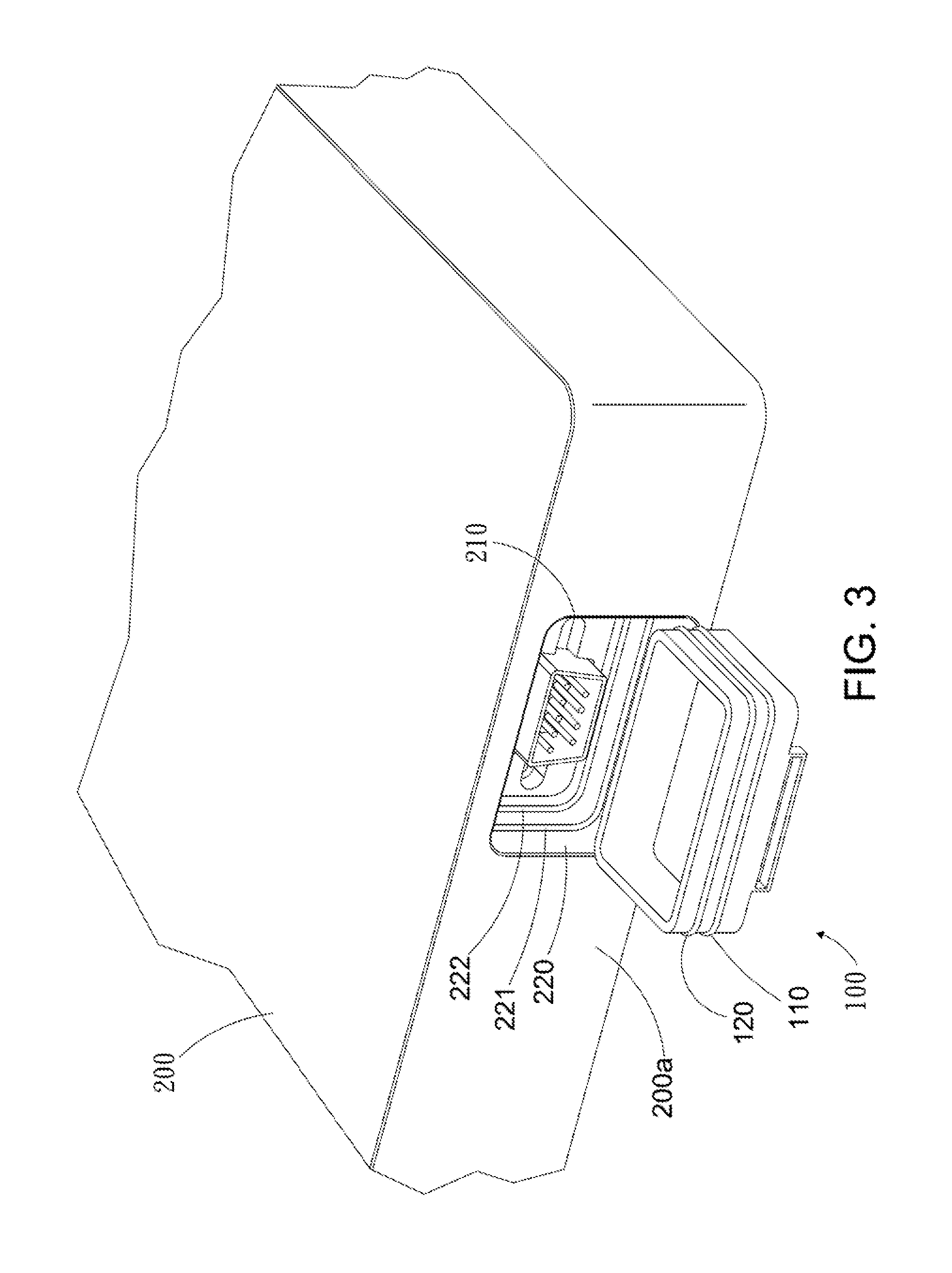
A waterproof assembly for an electronic device includes a watertight door and a case. The watertight door includes a cover, a water absorbing ring, and a water blocking ring. The cover is provided for being disposed into an opening of the case. The water absorbing ring and the water blocking ring are disposed between an outer peripheral surface of the cover and an inner peripheral surface defining the opening. The water absorbing ring includes deformable material and water absorbent, such that the water absorbing ring expands by absorbing water and contacts the inner and outer peripheral surfaces. The water blocking ring is normally compressed and contacts the inner and outer peripheral surfaces. When water penetrating occurs, the water block ring blocks water preliminarily, and then the water absorbing ring block blocks fully water after completely expanding.

Description

BACKGROUND OF THE INVENTION[0001]1. Field of the Invention[0002]The present invention relates to a waterproof assembly, and more particularly to a waterproof assembly for sealing an opening of a case of an electronic device.[0003]2. Related Art[0004]A portable electronic device for being operated outdoor, such as a rugged laptop computer, is often sprayed by water occasionally under adverse circumstances. Therefore, a portable electronic device or a rugged laptop computer must be waterproof, so as to preventing water from entering the interior of the device to short the electronic components and to damage the device.[0005]Generally, water entering a portable electronic device occurs in two ways. For one way, a case of the portable electronic device is combined by a plurality of members, so that slits may be generated on junctions between adjacent members, and thus water may run through the slits. For the other way, openings must be opened in the case, for disposing electrical connec...

Claims


Application Information

Patent Timeline
Patent Type & Authority Patents(United States)
IPC IPC(8): A47B95/00F16J15/02B65D43/04B65D51/00
CPCA45C5/03A45C13/008A45C13/04A45C15/00G06F1/1656H05K5/061A45C2011/003A45C2013/025
Inventor KUO, HSIU-YU
Owner GETAC TECH CORP
Learn More