Device for evaluating biochemical samples

a biochemical and sample technology, applied in the direction of biochemical instruments and processes, material testing goods, instruments, etc., can solve the problems of cost which is associated with image recording means and not correlated with cos

Active Publication Date: 2013-06-04
ASMAG HLDG
View PDF13 Cites 1 Cited by
  • Summary
  • Abstract
  • Description
  • Claims
  • Application Information

AI Technical Summary

Benefits of technology

[0006]The object of the invention is accordingly to construct a device for evaluating biochemical samples of the type described at the outset in such a way that simple constructional means can ensure reliable evaluation of the samples.
[0008]The use of a photoactive layer based on organic semiconductors results in comparatively simple design conditions based on the solubility of the organic semiconductor materials in conventional solutions. This means that an image recording means based on organic semiconductors can be attached to the carrier for the biochemical samples inexpensively compared to photodiodes or phototransistors based on inorganic semiconductors, and this allows direct allocation of the light-sensitive layer to the samples, so an optical lens system can advantageously be dispensed with. This applies not only to the recording of individual samples but also to the evaluation of a large number of samples which are attached to a carrier and to which light-sensitive elements have to be assigned in a matrix order corresponding to the order of samples.
[0011]If the spectral change, caused by a reaction of the samples with a reagent, in the absorption of light is observed, the samples can be illuminated from the side remote from the photoactive layer in order to detect the transmitted light and hence the absorption of light. However, such external illumination of the samples is not necessary if a reflection of light on the samples is used for this purpose. The same applies to the evaluation of radiation, for example fluorescent radiation, excited by light. In these cases, the light required for reflection or the light required for exciting the radiation of the correspondingly labelled biomolecules can be sent from a light-emitting layer on the side, remote from the samples, of the light-sensitive layer which is therefore to be translucent; this does not present any difficulties to the photoactive layer with regard to the use of organic semiconductors. The provision of a light-emitting layer on the side of the light-sensitive layer that is remote from the samples renders the device independent of external illumination conditions, and this broadens the range of possible uses and ensures simple handling.
[0013]If a respective photoactive layer is used for the light-sensitive and the light-emitting layer, the electrode layers can be separated from one another by an insulating layer on the mutually facing sides of the two photoactive layers. However, it is also possible to provide for the photoactive layer of the light-sensitive layer and the photoactive layer of the light-emitting layer a common electrode layer between the two layers, and this simplifies the design.
[0016]The output signals from the light-sensitive elements can be read out into the evaluation circuit as a function of the local position of the respectively activated light-emitting elements. In this case, it is possible to evaluate the samples individually or in groups as a function of the activation of the light-emitting elements, and this restricts the excitation energy to be provided for the light-emitting elements which, after all, can be successively activated in any desired sequence. In addition, the output signals from the light-sensitive elements can also be carried out as a function with respect to time of the activation of the light-emitting elements. This measure can ensure that the emitted light for exciting fluorescent radiation does not impair the measurement of the fluorescent radiation.

Problems solved by technology

The main drawback of this known device for evaluating biochemical samples is the cost which is associated with the image recording means and relates not only to the structural design of the image recording means but also to the optical lens system between the sample carrier and the image recording means, and also to the precise orientation of the sample carrier with respect to the lens system or the image recording means.

Method used


Image

  • Device for evaluating biochemical samples
  • Device for evaluating biochemical samples
  • Device for evaluating biochemical samples

Examples


Embodiment Construction

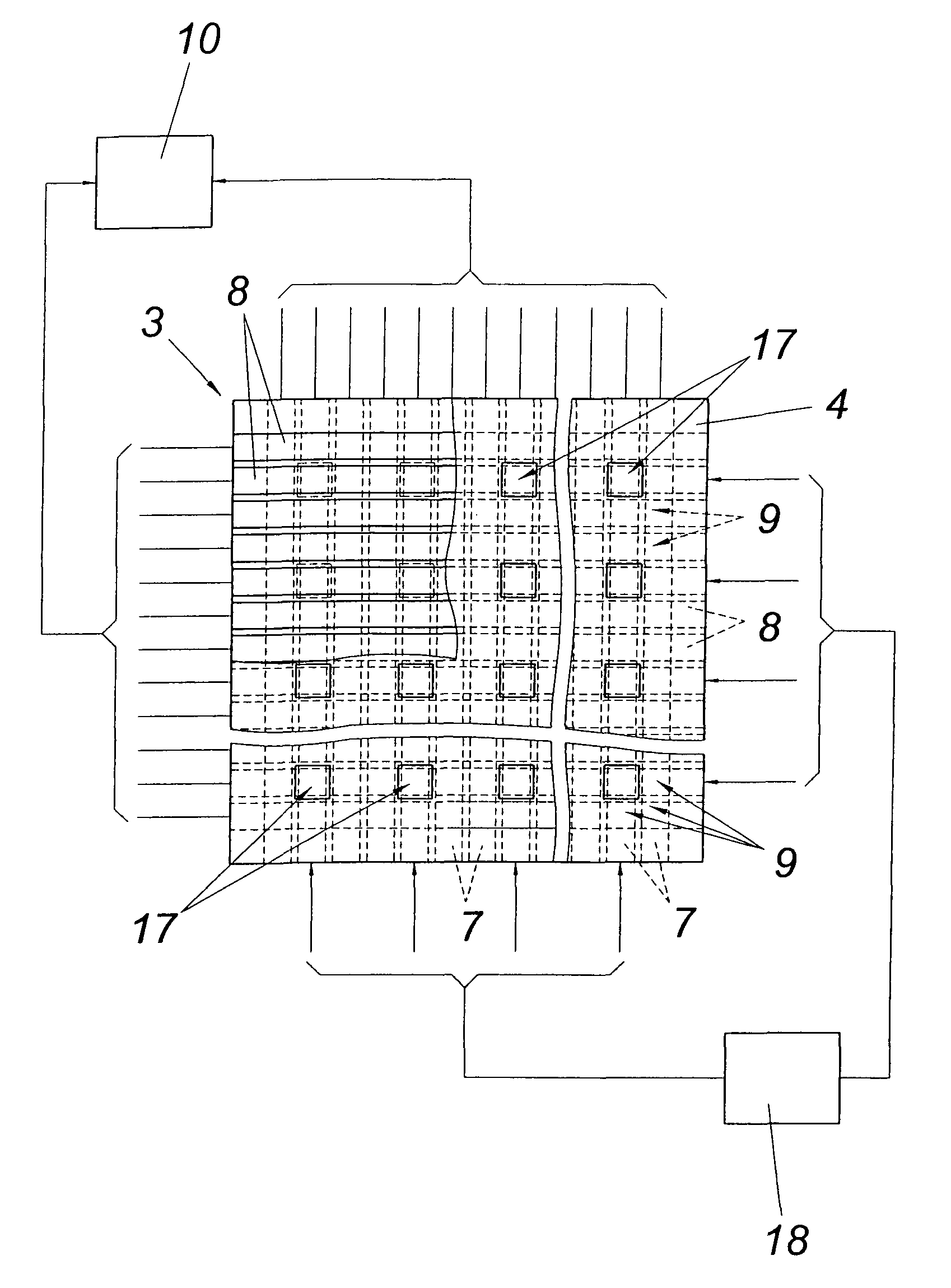
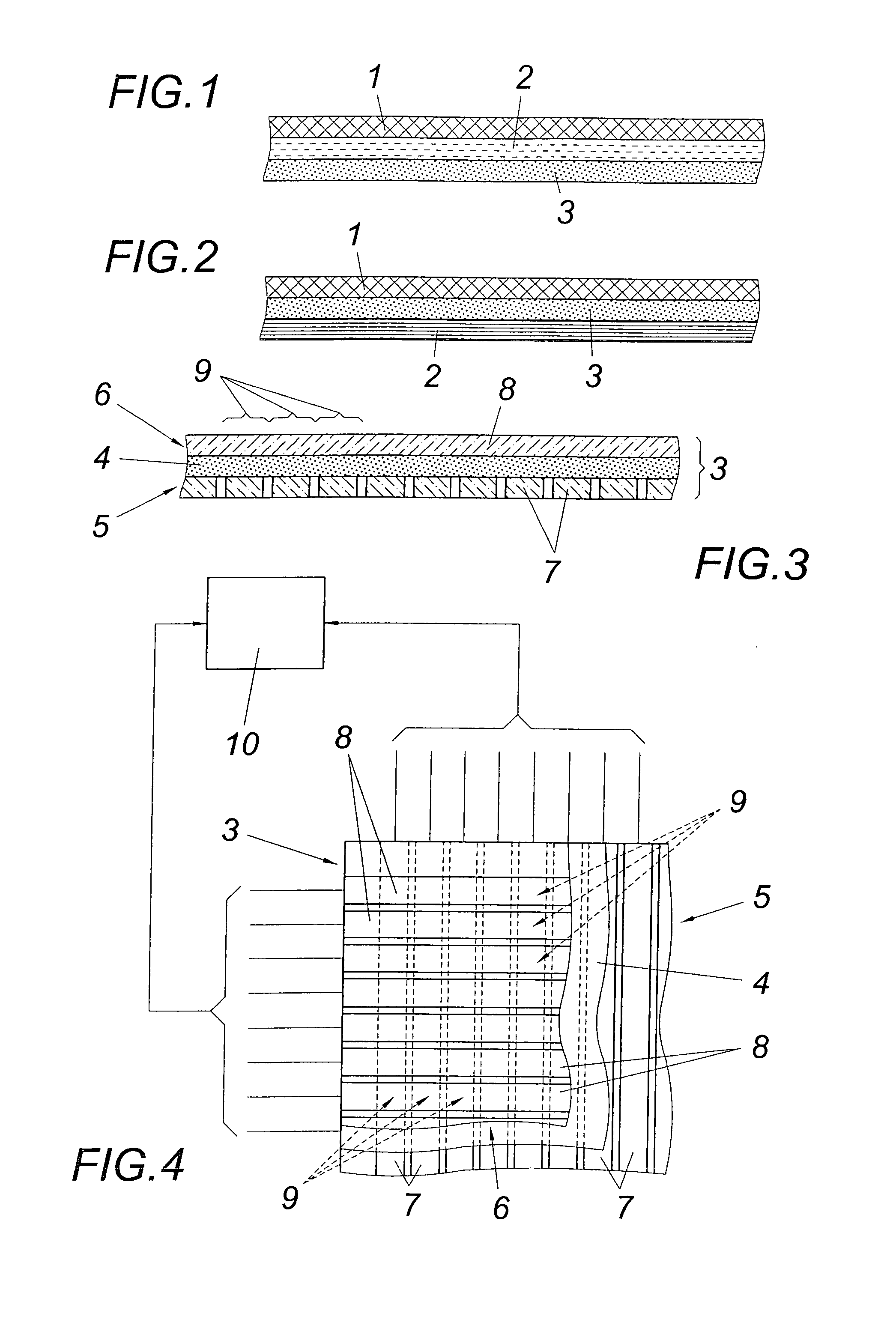
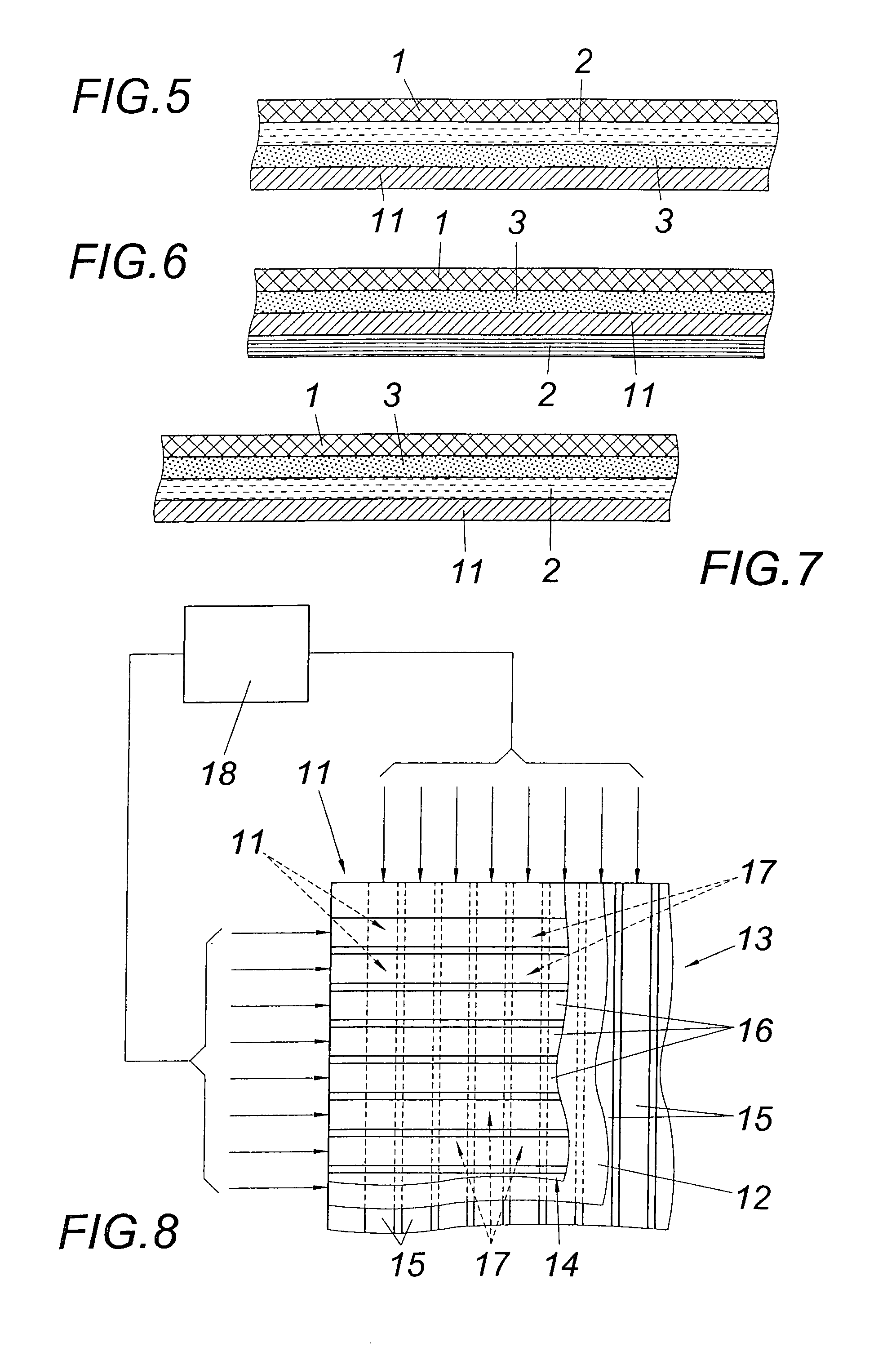
[0026]As shown in FIG. 1, the biochemical samples 1 to be evaluated are attached to a translucent sample carrier 2, either in the form of a continuous layer or in mutually separated regions. On the side of the translucent sample carrier 2 that is remote from the samples 1, there is provided a light-sensitive layer 3 allowing the spectral change, occurring in the event of a corresponding reaction of the samples with a reagent, in the absorption of light radiation to be determined by the detection of the transmitted light or fluorescent radiation, excited using light, of correspondingly labelled biomolecules. As may be seen from FIG. 2, the light-sensitive layer 3 can also be arranged between the samples 1 and the sample carrier 2, so the samples 1 are attached to the light-sensitive layer 3, an insulating layer optionally being interposed. In this case, the sample carrier 2 does not have to be translucent.

[0027]The light-sensitive layer 3 has, as shown in FIGS. 3 and 4, a photoactive...


PUM

PropertyMeasurementUnit
timeaaaaaaaaaa
fluorescentaaaaaaaaaa
solubilityaaaaaaaaaa

Abstract

Described is a device for evaluating biochemical samples (1), with a sample carrier (2), with an image recording means having a light-sensitive layer (3) connected to an evaluation circuit (10), and with a means for illuminating the samples (1). In order to provide simple design conditions, it is proposed that the light-sensitive layer (3), provided on the sample carrier (2), of the image recording means comprise a photoactive layer (4) based on organic semiconductors between two electrode layers (5, 6), of which the electrode layer (6) between the photoactive layer (4) and the samples (1) is translucent at least in certain regions.

Description

CROSS REFERENCE TO RELATED APPLICATIONS[0001]Applicants claim priority under 35 U.S.C. §119 of Austrian Application No. A 1502 / 2004 filed Sep. 8, 2004. Applicants also claim priority under 35 U.S.C. §365 of PCT / AT2005 / 000338 filed Aug. 24, 2005. The international application under PCT article 21(2) was not published in English.[0002]1. Field of the Invention[0003]The invention relates to a device for evaluating biochemical samples, with a sample carrier, with an image recording means having a light-sensitive layer connected to an evaluation circuit, and with a means for illuminating the samples.[0004]2. Description of the Prior Art[0005]The fact that in specific reactions between a biomolecular layer and a reagent a spectral change, discernible as a colour change, in the absorption of light occurs within the biomolecular layer or excitation with light causes correspondingly labelled biomolecules to emit, for example, fluorescent radiation can be used to investigate using an image re...

Claims


Application Information

Patent Timeline
Patent Type & Authority Patents(United States)
IPC IPC(8): G01N27/00
CPCG01N21/75H01L27/146G01N21/78G01N2201/0628
Inventor PADINGER, FRANZSCHROTER, KLAUS G.
Owner ASMAG HLDG
Why Eureka
Try Eureka