Arrangement for directing a lightning current within a wind turbine
a technology for wind turbines and lightning currents, applied in the direction of connection contact material, lighting conductors, coupling device connections, etc., can solve the problems of reducing the service life of the unit, reducing the number of different parts to be assembled in a confined space, and requiring free space near the components to mount the assembly, etc., to achieve the effect of reducing manufacturing and storage costs, reducing parts, and reducing complexity
- Summary
- Abstract
- Description
- Claims
- Application Information
AI Technical Summary
Benefits of technology
Problems solved by technology
Method used
Image
Examples
first embodiment
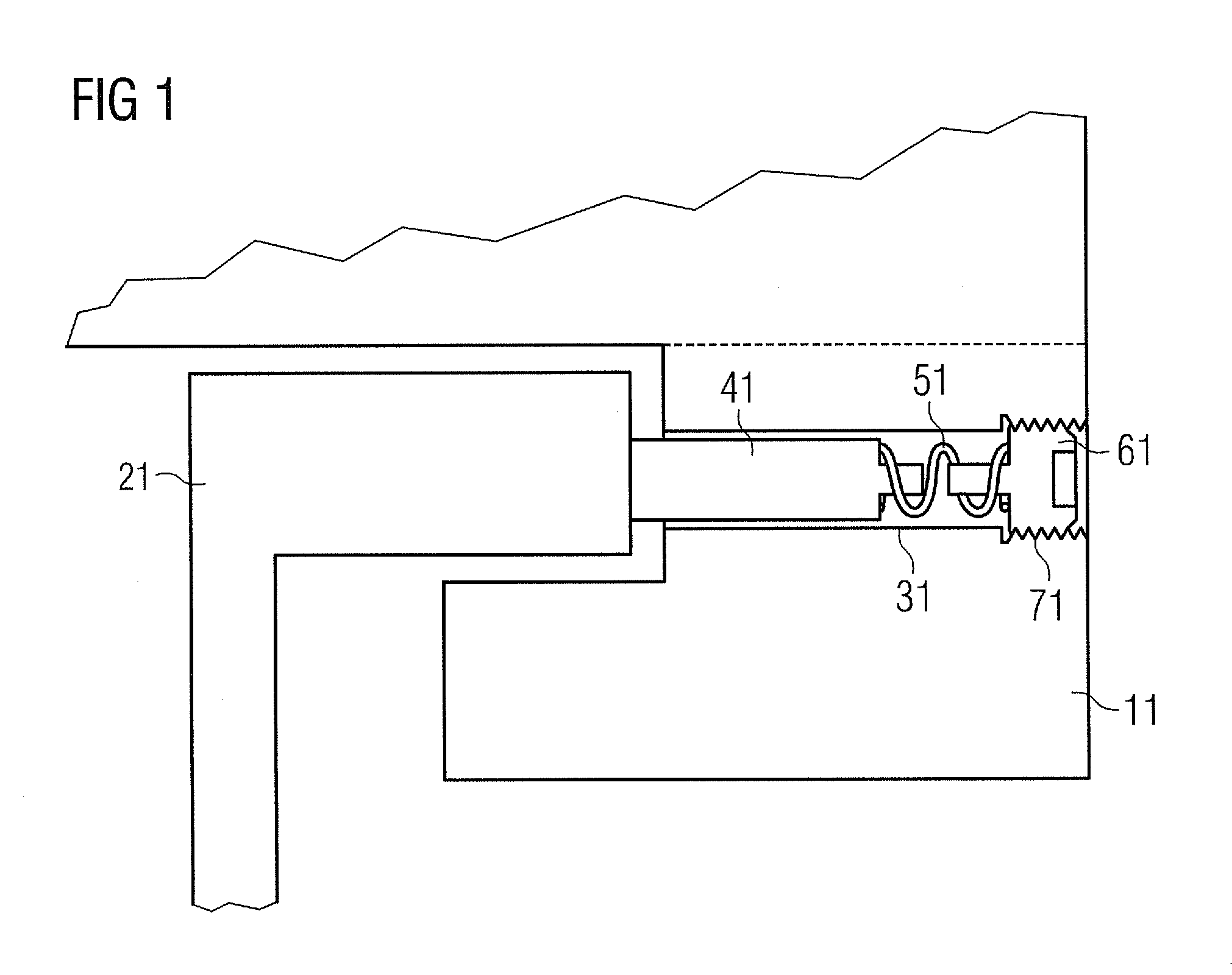
[0039]FIG. 1 illustrates a It shows a cross-sectional view of a part of a wind turbine comprising a first component, namely a yaw clamp 11 and a second component, namely a tower 21.
[0040]The yaw clamp 11 forms part of a yaw system which is mounted between the nacelle and the tower 21. The nacelle and the yaw clamp 11 are able to move on top of the tower 21.
[0041]In order to achieve a lightning protection effect, a contact element 41 is installed between the yaw clamp 11 and the tower 21.
[0042]The contact element 41 is mounted at least partly integrated in the yaw clamp 11 in radial direction. For this reason, a guideway 31 is provided in the yaw clamp 11. This guideway 31 is realised in form of a recess, for instance a radial hole. Alternatively, the guideway 31 may be constructed as a channel or as a groove.
[0043]A first end of this contact element 41 is pressed onto the tower 21 to form a sliding contact. The contact element 41 is either resilient by itself or mounted resiliently...
second embodiment
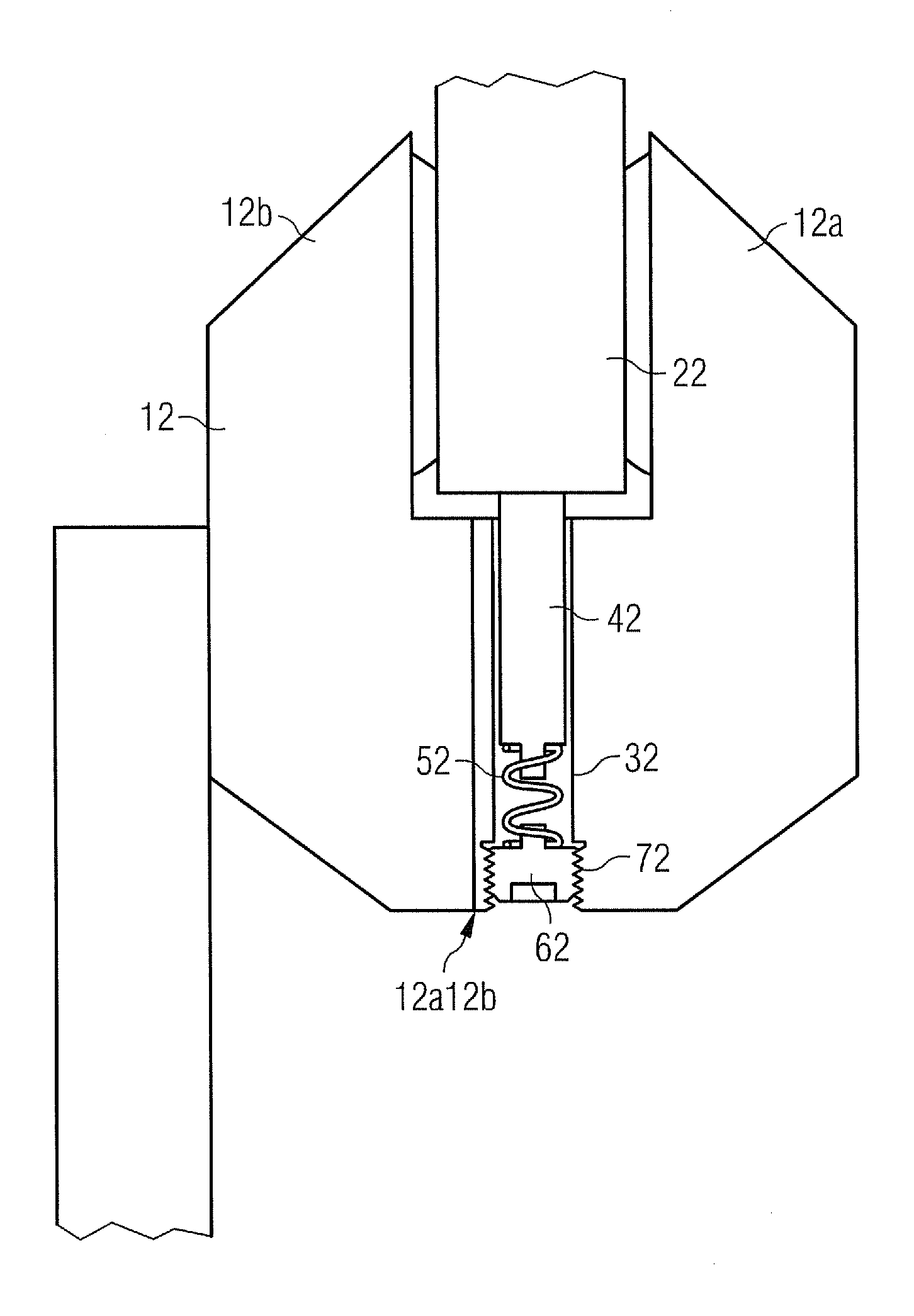
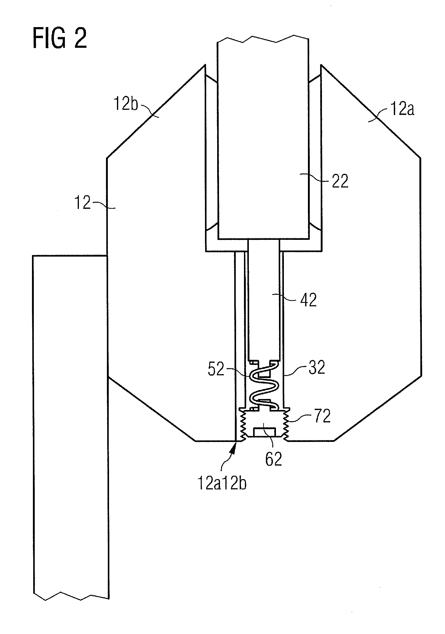
[0050]FIG. 2 illustrates a It shows a cross-sectional view of a part of a braking system of the wind turbine comprising a first component, namely a double acting brake calliper 12, within which a first component, namely a brake disc 22, is arranged. The brake calliper 12 comprises a first calliper half 12a and a second calliper half 12b.
[0051]In order to achieve a lightning protection effect, a contact element 42 is arranged between the brake calliper 12 and the brake disc 22.
[0052]The contact element 42 is mounted at least partly integrated in the brake calliper 12. For this reason, a guideway 32 is provided in the brake calliper 12. This guideway 32 is realised in form of a recess, for instance a radial hole. Alternatively, the guideway 32 may be constructed as a channel or as a groove.
[0053]In an embodiment of the invention, shown in FIG. 2, the guideway 32 is provided near the calliper set divide 12a12b.
[0054]As aforementioned, the brake calliper 12 comprises a first calliper...
PUM
 Abstract
Description
Claims
Application Information
 - R&D
- Intellectual Property
- Life Sciences
- Materials
- Tech Scout
- Unparalleled Data Quality
- Higher Quality Content
- 60% Fewer Hallucinations
Browse by: Latest US Patents, China's latest patents, Technical Efficacy Thesaurus, Application Domain, Technology Topic, Popular Technical Reports.
© 2025 PatSnap. All rights reserved.Legal|Privacy policy|Modern Slavery Act Transparency Statement|Sitemap|About US| Contact US: help@patsnap.com


