Control device for electric vehicle

a technology for electric vehicles and control devices, which is applied in battery/fuel cell control arrangements, safety/protection circuits, instruments, etc., can solve the problems of reducing the functionality of high-voltage batteries such as the decrease of charging capacity, the loss of accessories driven by high-voltage batteries, and the loss of high-voltage batteries. , to achieve the effect of reducing torque output, reducing the torque output of the drive motor, and reducing the energy capacity of the high-voltag

Active Publication Date: 2013-06-11
SUBARU CORP
View PDF3 Cites 4 Cited by
  • Summary
  • Abstract
  • Description
  • Claims
  • Application Information

AI Technical Summary

Benefits of technology

[0012]According to the control device for an electric vehicle of the present invention, the threshold storing unit is provided which stores two large and small thresholds (first threshold>second threshold) and the drive state switching unit is provided which reduces torque output of the drive motor while allowing the accessories to operate when the detection signal from the remaining energy capacity detecting unit falls below the first threshold, and stops power supply to the drive motor while allowing the accessories to operate when the detection signal from the remaining energy capacity unit falls below the second threshold. Therefore, when the remaining energy capacity of the high-voltage battery becomes low, it is possible so reduce torque output to the drive motor and then to stop power supply thereto, while driving the accessories. Accordingly, even when the energy capacity of the high-voltage battery becomes low and the electric vehicle enters a driving impossible state, it is possible continuously to drive the accessories. As a result, when, for example, the remaining energy capacity of the high-voltage battery becomes low while the electric vehicle is driving on a downhill, the drive state of the accessories assisting she driver's operation dose not become low, which does not give anxiety to the driver.
[0013]According to the control device for an electric vehicle of the present invention, the third threshold which is smaller than the second threshold and the lower limit of the remaining energy capacity of the high-voltage battery is stored in the threshold storing unit, and the drive state switching unit stops the operation of the accessories when the detection signal falls below the third threshold. Therefore, it is possible to prevent the high-voltage battery from entering a deep discharge state, and thus from being damaged.

Problems solved by technology

However, due to the its nature, when the remaining energy capacity (SOC) of the high-voltage battery substantially decreases and the high-voltage battery enters a deep discharge state, decreased functionality of the high-voltage battery such as decrease in charging capacity occur.
However, according to the control logic of the control device for an electric vehicle described Patent Document 1, when the remaining energy capacity of the high-voltage battery becomes low, and, for example, the electric vehicle enters a state such that it stops (driving impossible state), the accessories driven by the high-voltage battery may also stop.
On the other hand, when the accessories stop while the electric vehicle is driving on a downhill, the electric vehicle exhibits an acceleration behavior but the operational performance of accessories assisting the driver's operation becomes low, which may give anxiety to the driver.

Method used


Image

  • Control device for electric vehicle
  • Control device for electric vehicle
  • Control device for electric vehicle

Examples


Embodiment Construction

[0017]An embodiment of the present invention will hereunder be described with reference to the drawings.

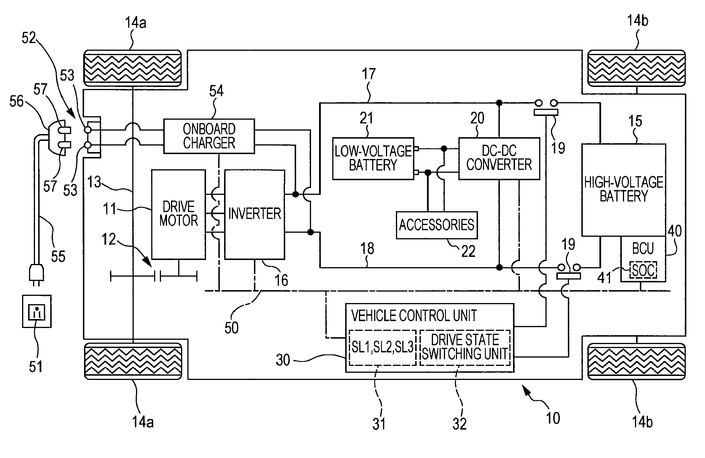
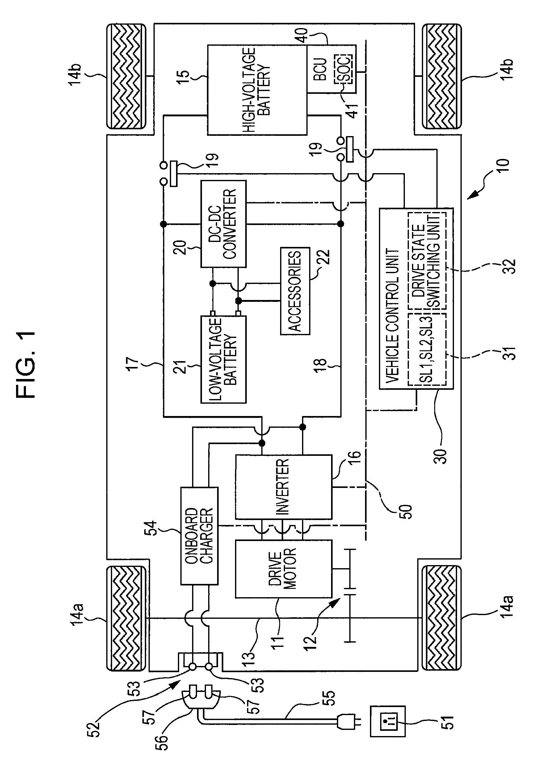
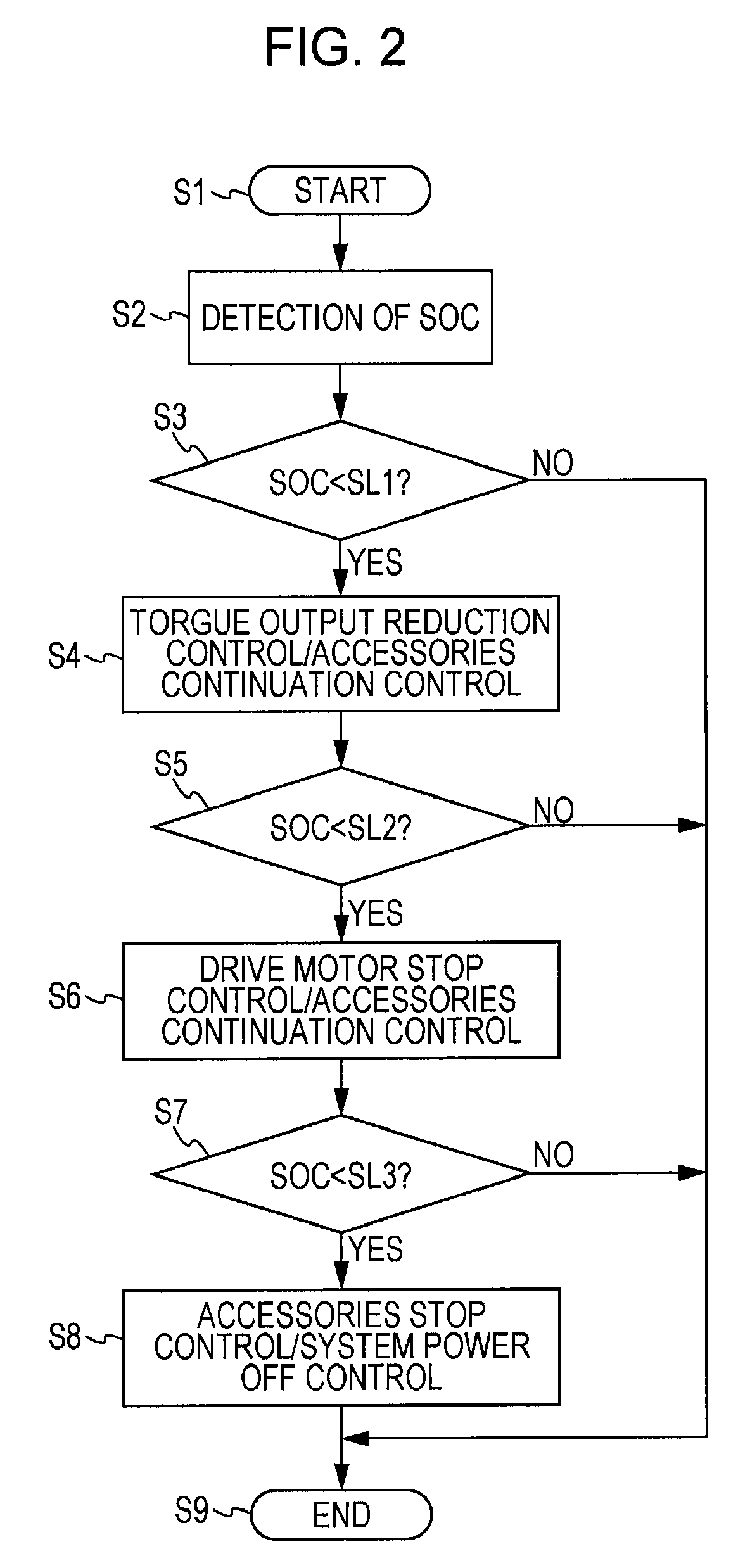
[0018]FIG. 1 is a schematic diagram of the configuration of an electric vehicle. FIG. 2 is a flow chart showing contents of control (operation) of a control device in the electric vehicle. FIG. 3 is a graph showing a change in the remaining energy capacity according to the present invention and a change in the remaining energy capacity according to a conventional technology.

[0019]As shown in FIG. 1, an electric vehicle 10 is equipped with a drive motor 11 that is comprised of a three-phase DC motor. A driveshaft 13 is connected to the drive motor 11 by the intermediary of a gear train 12. A pair of front wheels 14a is co-rotatably provided at the both ends of driveshaft 12. The electric vehicle 10 has a pair of rear wheels 14b, and thus the electric vehicle of the present embodiment is a four-wheel drive vehicle equipped with she front wheels 14a and rear wheels 14b. As seen above...


PUM


Abstract

A control device for an electric vehicle where a threshold storing unit is provided which stores two large and small thresholds and (first threshold>second threshold), and a drive state switching unit is provided which reduces torque output of a drive motor, while allowing accessories to operate, when a remaining energy capacity SOC from a remaining energy capacity detecting unit fails below the first threshold, and stops power supply to the drive motor, while allowing the accessories to operate, when the remaining energy capacity SOC from a remaining energy capacity detecting unit falls below the second threshold.

Description

CROSS REFERENCES TO RELATED APPLICATIONS[0001]The present application claims priority from Japanese Patent Application No. 2010-032180 filed on Feb. 17, 2010, the entire contents of which are hereby incorporated by reference.BACKGROUND OF THE INVENTION[0002]1. Field of the Invention[0003]The present invention relates to a control device for an electric vehicle that controls electric power from a high-voltage battery to drive a drive motor and accessories.[0004]2. Description of the Related Art[0005]An electric vehicle is equipped with a high-voltage battery comprised of a lithium-ion rechargeable battery, nickel metal hydride rechargeable battery or the like, and a drive motor comprised of a three-phase DC motor, PM motor or the like. Electric power from the high-voltage battery (approximately 300 volts) is power converted by an inverter that is controlled by a vehicle control unit and provided to the drive motor. In addition, electric power from the high-voltage battery is stepped ...

Claims


Application Information

Patent Timeline
Patent Type & Authority Patents(United States)
IPC IPC(8): B60L15/20
CPCB60L1/00B60L11/1859B60L11/1861Y02T10/7005Y02T10/7258Y02T10/7044Y02T10/705B60L2200/26H02J2007/004B60L58/14H02J7/00306Y02T10/70Y02T10/72
Inventor SETA, ITARUOHTOMO, YOSUKE
Owner SUBARU CORP
Why Eureka
Try Eureka