Torque-handling gear with teeth mounted on flexible arms

a flexible arm and torque-handling technology, applied in the field of rackandpinion gear sets, can solve the problems of less torque, noise and vibration, and limited hertzian contact stress of most gears used today, and achieve the effect of efficient torque-transferring

Active Publication Date: 2013-06-25
NOWICKI ANDREW
View PDF28 Cites 15 Cited by
  • Summary
  • Abstract
  • Description
  • Claims
  • Application Information

AI Technical Summary

Benefits of technology

[0012]A gear having flexible teeth addresses many of these problems with conventional gearing. Such a gear may form the first gear of a gear set that includes a second gear, to allow for efficiently transferring torque between the gears. Such a gear having flexible teeth includes a hub having an axis and a first periphery.
[0016]When the arm angle is greater than 0°, the teeth will deflect both radially and tangentially. The radial deflection allows teeth with circular profiles to function properly. The tangential deflection is valuable because it assures that every meshing tooth and its arm share the load with other arms on its gear whether the teeth have circular or involute profiles.
[0017]This arrangement allows two or more teeth on one of the gears to simultaneously contact and transfer force to the other gear's teeth. Allowing a number of teeth to share the force transferred from one gear to the other reduces the Hertzian contact stress in each of the meshing teeth and therefore increases the torque-transferring capacity of the gear set. The load sharing by several arms and teeth allows a gear of this construction to handle higher torque than Hertzian contact stress would otherwise allow.

Problems solved by technology

Because of unavoidable deviations from the ideal in the gears' shapes, at any given instant a single tooth on each gear transfers almost all of the torque at any given time, or at least much of the time.
Hertzian contact stress limits high-speed torque ratings of most gears used today.
All gears can handle less torque at high speeds than at low speeds because of vibration and higher impact loading at higher speeds.
Further, stiff materials do not damp vibration well, so conventional gears generate noise and vibration.
Gears made of inexpensive plastics having a low modulus of elasticity and low strength compared to metals are much better at damping vibration, but cannot carry much torque.
Gears made of plastics reinforced with high-strength fibers have the intrinsic capacity to carry high torque, but they resist Hertzian contact stress poorly.
But even circular profiles cannot ensure large surface contact between the gear teeth because their rigidity cannot compensate for inherent misalignments and incompatibilities of various types.

Method used


Image

  • Torque-handling gear with teeth mounted on flexible arms
  • Torque-handling gear with teeth mounted on flexible arms
  • Torque-handling gear with teeth mounted on flexible arms

Examples


Embodiment Construction

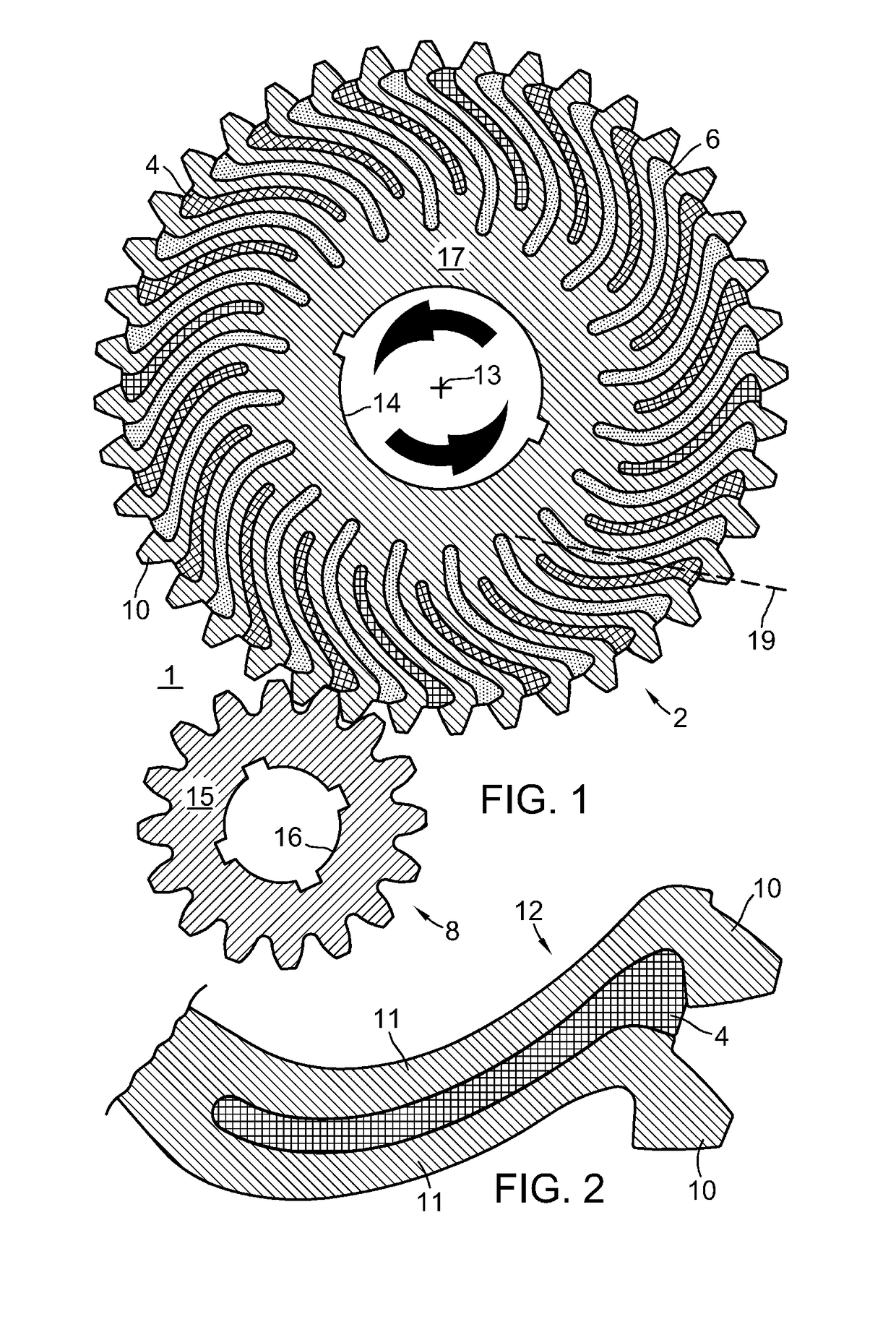
[0045]FIG. 1 shows a gear set 1 comprising a gear 2 meshing with a pinion gear 8 for transmitting torque between them. In this example, gear 2 rotates in the direction indicated by the arrows about an axis 13 and drives gear 8. Gears 2 and 8 have respectively, hubs 17 and 15 with central openings 14 and 16 for mounting on shafts for rotation. Gears 2 and 8 lie in a gear plane coincident with the paper plane for FIG. 1.

[0046]FIG. 2 shows two individual tooth-arm units 12, each tooth-arm unit 12 comprising a tooth 10 mounted or attached on the outside end of a slender spiral arm 11 forming a cantilevered beam. The thinness of arms 11 relative to their length allow arms 11 to flex elastically under load, allowing teeth 10 to shift both radially and tangentially. That is, teeth 10 will under load, shift in any direction within the gear plane because of the flexibility of arm 11.

[0047]In FIG. 1, each arm 11 is integral with hub 17 at an attachment point. A line 19 drawn between the attac...


PUM

PropertyMeasurementUnit
acute angleaaaaaaaaaa
arm angleaaaaaaaaaa
angleaaaaaaaaaa

Abstract

First gear for use in a gear set including a second gear has a hub to which are attached a plurality of arms made of an elastic material. Each pair of adjacent arms defines a slot between them into which the arms may bend. The arms can deflect elastically in the plane as a cantilevered beam. Each arm has on the end thereof, a tooth for meshing with a tooth on the second gear to allow transfer of force between the first gear's tooth and the meshing second gear's tooth. A load distributor in contact with at least first and second arms distributes to the second arm at least a portion of force received by the first arm's tooth while the first arm's tooth meshes with a tooth on the second gear. In one embodiment, the load distributor comprises an insert within the slot between the first and second arms.

Description

[0001]This application is a U.S. National Stage Filing under 35 U.S.C. 371 from international patent application Serial No. PCT / US2009 / 036553, filed on Mar. 9, 2009 under 35 U.S.C. §363, published on Sep. 17, 2009 as WO 2009 / 114477 A2, and republished as WO 2009 / 114477 A3, claiming priority under 35 U.S.C. §119(e)(1) to U.S. provisional patent appl. ser. No. 61 / 035,055, filed Mar. 10, 2008, said applications and publications incorporated herein by reference in their entirety.FIELD OF THE INVENTION[0002]The present invention pertains to gears for handling and transferring torque. One embodiment is a rack-and-pinion gear set useful for supporting and driving a rail car.BACKGROUND OF THE INVENTION[0003]The teeth of conventional gears for handling and transferring torque usually comprise hard and rigid metal, typically steel. Individual teeth are so short along the radii relative to their tangential dimension that tangential deflection is imperceptible.[0004]Teeth on gears usually have ...

Claims


Application Information

Patent Timeline
Patent Type & Authority Patents(United States)
IPC IPC(8): F16H55/17
CPCF16H55/16F16H55/30F16H2055/306Y10T74/19884Y10T29/49476Y10T74/19967Y10T74/19633
Inventor NOWICKI, ANDREW
Owner NOWICKI ANDREW
Why Eureka
Try Eureka