Method and apparatus for treating a hip joint, including the provision and use of a novel suture passer

a technology of hip joint and suture passer, which is applied in the field of surgical methods and equipment, can solve the problems of significant interference with patient comfort and lifestyle, pathology so severe that it is necessary to have partial or total hip replacement, and the scope of procedures is generally limited

Active Publication Date: 2013-06-25
STRYKER CORP
View PDF35 Cites 26 Cited by
  • Summary
  • Abstract
  • Description
  • Claims
  • Application Information

AI Technical Summary

Benefits of technology

[0039]The present invention provides a novel method and apparatus for passing suture through the fibrous capsule in a suturing operation, thereby making it more practical for a surgeon to arthroscopically operate on the hip joint by first laying open the fibrous capsule, performing the desired procedure on the hip joint, and then closing the fibrous capsule by suturing at the conclusion of the procedure.

Problems solved by technology

In other cases, the pathology may be minor at the outset but, if left untreated, may worsen over time.
The pathology may, either initially or thereafter, significantly interfere with patient comfort and lifestyle.
In some cases, the pathology can be so severe as to require partial or total hip replacement.
A number of procedures have been developed for treating hip pathologies short of partial or total hip replacement, but these procedures are generally limited in scope due to the significant difficulties associated with treating the hip joint.
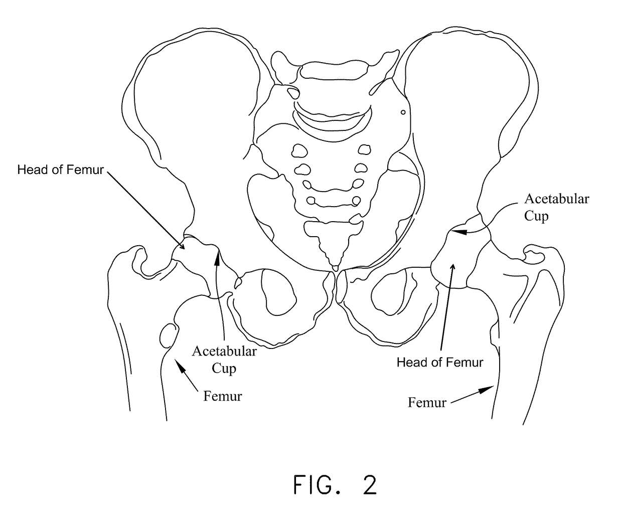
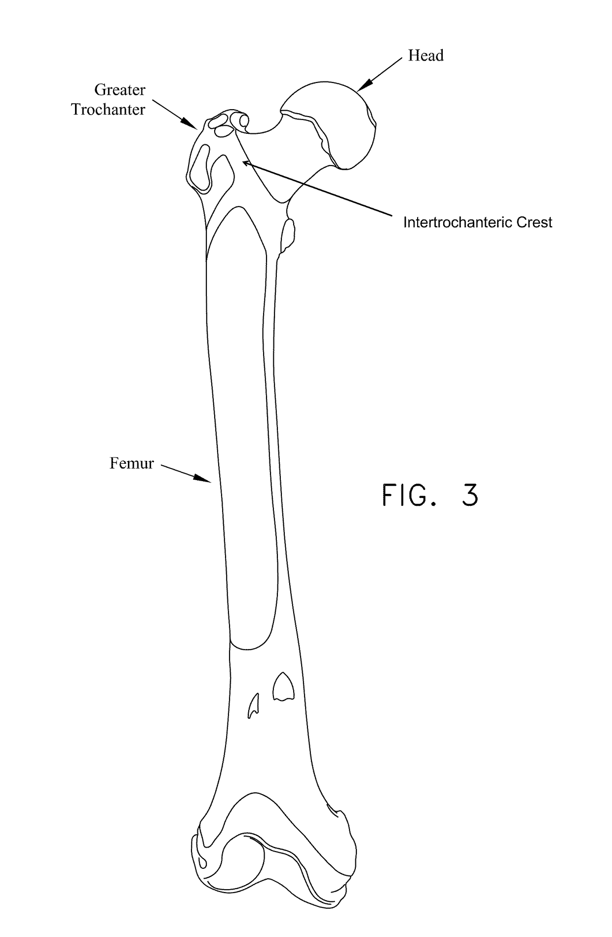
In some cases, and looking now at FIG. 13, this impingement can occur due to irregularities in the geometry of the femur.
In other cases, and looking now at FIG. 14, the impingement can occur due to irregularities in the geometry of the acetabular cup.
Impingement can result in a reduced range of motion, substantial pain and, in some cases, significant deterioration of the hip joint.
Defects of this type sometimes start out fairly small but often increase in size over time, generally due to the dynamic nature of the hip joint and also due to the weight-bearing nature of the hip joint.
Articular defects can result in substantial pain, induce and / or exacerbate arthritic conditions and, in some cases, cause significant deterioration of the hip joint.
More particularly, in many cases, an accident or sports-related injury can result in the labrum being torn away from the rim of the acetabular cup, typically with a tear running through the body of the labrum.
These types of injuries can be very painful for the patient and, if left untreated, can lead to substantial deterioration of the hip joint.
Unfortunately, minimally-invasive treatments for pathologies of the hip joint have lagged far behind minimally-invasive treatments for pathologies of the shoulder joint and the knee joint.
As a result, it is relatively difficult for surgeons to perform minimally-invasive procedures on the hip joint.
This limited access further complicates effectively performing minimally-invasive procedures on the hip joint.
In addition to the foregoing, the nature and location of the pathologies of the hip joint also complicate performing minimally-invasive procedures on the hip joint.
This makes drilling into bone, for example, significantly more complicated than where the angle of approach is effectively aligned with the angle at which the instrument addresses the tissue, such as is frequently the case in the shoulder joint.
Furthermore, the working space within the hip joint is typically extremely limited, further complicating repairs where the angle of approach is not aligned with the angle at which the instrument addresses the tissue.
As a result of the foregoing, minimally-invasive hip joint procedures are still relatively difficult to perform and relatively uncommon in practice.
Consequently, patients are typically forced to manage their hip pain for as long as possible, until a resurfacing procedure or a partial or total hip replacement procedure can no longer be avoided.
These procedures are generally then performed as a highly-invasive, open procedure, with all of the disadvantages associated with highly-invasive, open procedures.
While the fibrous capsule provides an important function in encapsulating the hip joint, it also presents a significant obstacle to arthroscopically treating pathologies of the hip joint.
However, the penetration of this tough physical barrier must be effected very carefully, since the anatomical structures which are located immediately below the fibrous capsule are frequently delicate and sensitive to damage.
As a result, the workspace located between the fibrous capsule and the underlying bone is typically quite limited, thereby presenting significant visualization and operational challenges to the surgeon.
By way of example but not limitation, arthroscopic treatment of cam-type femoroacetabular impingement (i.e., cam-type FAI) is significantly complicated by the limited workspace present within the fibrous capsule.
However, the lack of workspace between the overlying fibrous capsule and the underlying femur can make such debridement procedures technically challenging for even the most experienced surgeons, because it can severely limit the field of vision within the workspace and inhibit proper positioning of the burr.
However, heretofore, it has been technically challenging to arthroscopically suture closed the laid-open fibrous capsule at the conclusion of the therapeutic procedure.
This is largely because (i) the workspace present at the remote surgical site is quite limited, and (ii) the fibrous capsule is made up of unusually tough tissue, which can make it extremely difficult to arthroscopically pass suture through the fibrous capsule in the suturing operation.

Method used


Image

  • Method and apparatus for treating a hip joint, including the provision and use of a novel suture passer
  • Method and apparatus for treating a hip joint, including the provision and use of a novel suture passer
  • Method and apparatus for treating a hip joint, including the provision and use of a novel suture passer

Examples


Embodiment Construction

[0109]Looking first at FIGS. 16 and 17, there is shown a novel suture passer 5 formed in accordance with the present invention. Suture passer 5 generally comprises an elongated shaft 10 having a distal jaw 15 disposed at the distal end of elongated shaft 10 and a handle 20 disposed at the proximal end of elongated shaft 10.

[0110]Looking next at FIGS. 18-25, distal jaw 15 is intended to releasably carry a suture 25 thereon. To this end, and as will hereinafter be discussed in further detail, distal jaw 15 has a suture slot 30 (FIG. 18) formed therein. In one preferred form of the present invention, suture slot 30 is sized so that suture 25 can slide easily therein. And in one preferred form of the present invention, suture slot 30 comprises a proximal longitudinal section 35, an intermediate diagonal section 40, and a distal longitudinal section 45. Distal jaw 15 also includes a slot 50 (FIG. 20) at its distal end. A distal jaw spring 55 (FIG. 19) is movably mounted in slot 50. More ...


PUM


Abstract

A suture passer including a shaft having an axis; a first jaw mounted to the shaft in alignment with the axis, the first jaw being configured to releasably support a length of suture thereon; a second jaw movably mounted to the shaft; and a needle movably mounted to the shaft, the needle having a hook and being configured to reciprocate in alignment with the axis so that the hook can selectively pass by the second jaw and engage suture releasably supported on the first jaw; wherein the first jaw includes a spring for selectively binding the suture to the first jaw.

Description

REFERENCE TO PENDING PRIOR PATENT APPLICATIONS[0001]This patent application claims benefit of:[0002](i) pending prior U.S. Provisional Patent Application Ser. No. 61 / 270,985, filed Jul. 15, 2009 by Scott Heneveld et al. for METHOD AND APPARATUS FOR ACCESSING THE INTERIOR OF A HIP JOINT, INCLUDING THE PROVISION AND USE OF A NOVEL DOUBLE SUTURE PASSER; and[0003](ii) pending prior U.S. Provisional Patent Application Ser. No. 61 / 327,431, filed Apr. 23, 2010 by David Skinlo et al. for METHOD AND APPARATUS FOR ACCESSING THE INTERIOR OF A HIP JOINT, INCLUDING THE PROVISION AND USE OF A NOVEL SUTURE PASSER.[0004]The two (2) above-identified patent applications are hereby incorporated herein by reference.FIELD OF THE INVENTION[0005]This invention relates to surgical methods and apparatus in general, and more particularly to surgical methods and apparatus for treating a hip joint.BACKGROUND OF THE INVENTIONThe Hip Joint In General[0006]The hip joint is a ball-and-socket joint which movably co...

Claims


Application Information

Patent Timeline
Patent Type & Authority Patents(United States)
IPC IPC(8): A61B17/04
CPCA61B17/0469A61B17/0482A61B17/0483A61B2017/2944A61B2017/06042A61B2017/06052A61B2017/2926A61B17/0485A61B17/06004
Inventor SKINLO, DAVIDHENEVELD, SCOTTWEISEL, THOMASPISARNWONGS, ROGER
Owner STRYKER CORP
Why Eureka
Try Eureka