Controllable energy utilization system and associated method

a technology of energy utilization and controllable energy, applied in the integration of power network operation systems, emergency power supply arrangements, transportation and packaging, etc., can solve problems such as electric power outag

Active Publication Date: 2013-06-25
GENERAL ELECTRIC CO
View PDF33 Cites 21 Cited by
  • Summary
  • Abstract
  • Description
  • Claims
  • Application Information

AI Technical Summary

Benefits of technology

[0011]In one embodiment, a system includes an energy source capable of providing electrical power for a supply period, and the energy source does not provide power during one or more non-supply periods, and the non-supply period is intermittent periods or unpredictable; a power backup unit coupleable to a load in response to a demand during the non-supply period; an energy storage system coupled to an energy converter; and a controller that controls the power back-up unit. The controller can cause the system to retain a dynamic determined power reserve level based on one or more of a usage rate, a capacity of the energy storage system, a state of charge of the energy storage system, a hazard warning indicative of an outage or a forecast outage. The controller can cause the system to expend at least a portion of the determined power reserve level to i.) generate an economic advantage relative to consuming power from the energy source, and ii.) maintain a statistical uptime level greater than a determined threshold. The controller can cause the system to charge the energy storage system from the energy converter to generate an economic advantage relative to consuming power from the energy source.

Problems solved by technology

Sometimes, there may be an electrical power outage.
These power outages may be due to performance of power grid systems or to natural or man-made causes.

Method used


Image

  • Controllable energy utilization system and associated method
  • Controllable energy utilization system and associated method
  • Controllable energy utilization system and associated method

Examples


Embodiment Construction

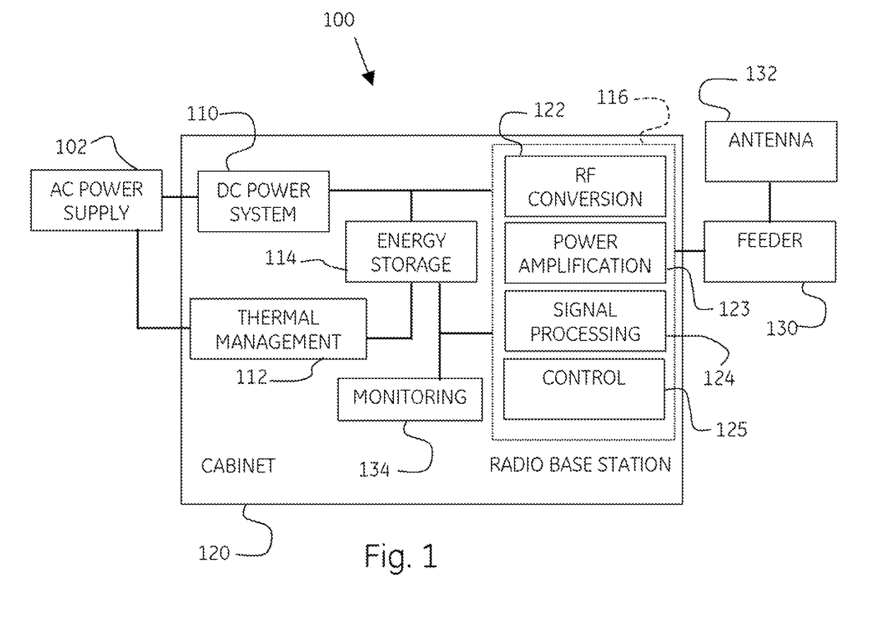
[0018]Embodiments of the invention may relate to a system for the utilization of energy. Embodiments of the invention may relate to a method of using a system for the utilization of energy.

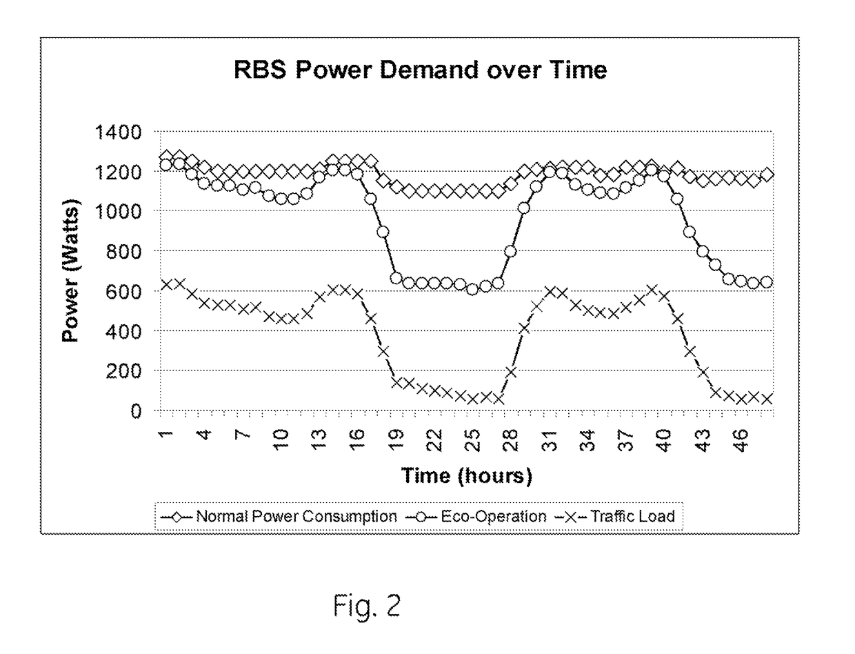
[0019]As used herein, “arbitrage”, or sometimes “energy arbitrage”, means a method of storing energy when electricity is being produced beyond current demand (and / or prices are relative low), and distributing energy when demand for electricity is high (and / or prices are relatively high). Peak means the usage is at a relative high point over a determined period. As used herein, the period associated with the Peak is a day unless context or language indicates otherwise. Similarly, the term Off-Peak refers to the relative low point over the determined period. Energy storage systems include batteries, flow cells, fuel cells, capacitors, fly wheels, and the like. Batteries, unless specified otherwise, include sodium metal halide, sodium sulfur, nickel metal hydride, nickel cadmium, lithium, zinc, and l...


PUM


Abstract

A system includes an energy storage system capable of receiving electrical energy from an energy source and can supply electrical energy to a first load during a first period and to the first load during a second period. The first load differs in usage rate from the first period relative to the second period. A system controller maintains the energy storage system such that the energy storage system maintains a first amount of stored electrical energy during a first mode, and a second amount of electrical energy during a second mode. The system controller maintains the energy storage system in the first mode during a first portion of the first period, and in the second mode during a second portion of the first period.

Description

CROSS REFERENCE TO RELATED APPLICATIONS[0001]This application is a non-provisional application that claims benefit and priority to provisional patent application Ser. No. 61 / 257,462 filed on 2 Nov. 2009, the disclosures of which are incorporated herein by reference in their entirety.BACKGROUND[0002]1. Technical Field[0003]Embodiments of the invention may relate to a system for the utilization of energy. Embodiments of the invention may relate to a method of using a system for the utilization of energy and energy storage.[0004]2. Discussion of Art[0005]It may be desirable to have access and continuity of service for high quality electrical power. Sometimes, there may be an electrical power outage. These power outages may be due to performance of power grid systems or to natural or man-made causes. It may be desirable to eliminate or reduce the impact of breaks in the continuity of service felt by the end-user. Industrial electrical power backup power systems may provide continuity of...

Claims


Application Information

Patent Timeline
Patent Type & Authority Patents(United States)
IPC IPC(8): H02J7/00H02J9/00
CPCH02J3/28H02J9/062H02J2003/146Y02B10/72Y04S20/224H02J2310/64Y02B10/70Y04S20/222Y04S50/10Y02B70/3225
Inventor PATEL, PRANAV N.MCCLINTIC, SHAWN A.
Owner GENERAL ELECTRIC CO
Why Eureka
Try Eureka