
Mineral composite beverage brewing cup and cartridge

a technology of mineral composite and beverage brewing, which is applied in the direction of packaging, packaging foodstuffs, packaged goods, etc., can solve the problems of reducing the rigidity and strength of the base, sidewalls buckling inward during the piercing process, and similar buckling may occur

Active Publication Date: 2013-07-02
BEMIS COMPANY INC
View PDF34 Cites 68 Cited by
  • Summary
  • Abstract
  • Description
  • Claims
  • Application Information

AI Technical Summary

Benefits of technology

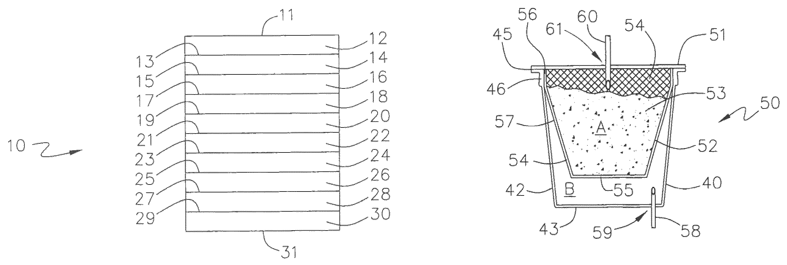
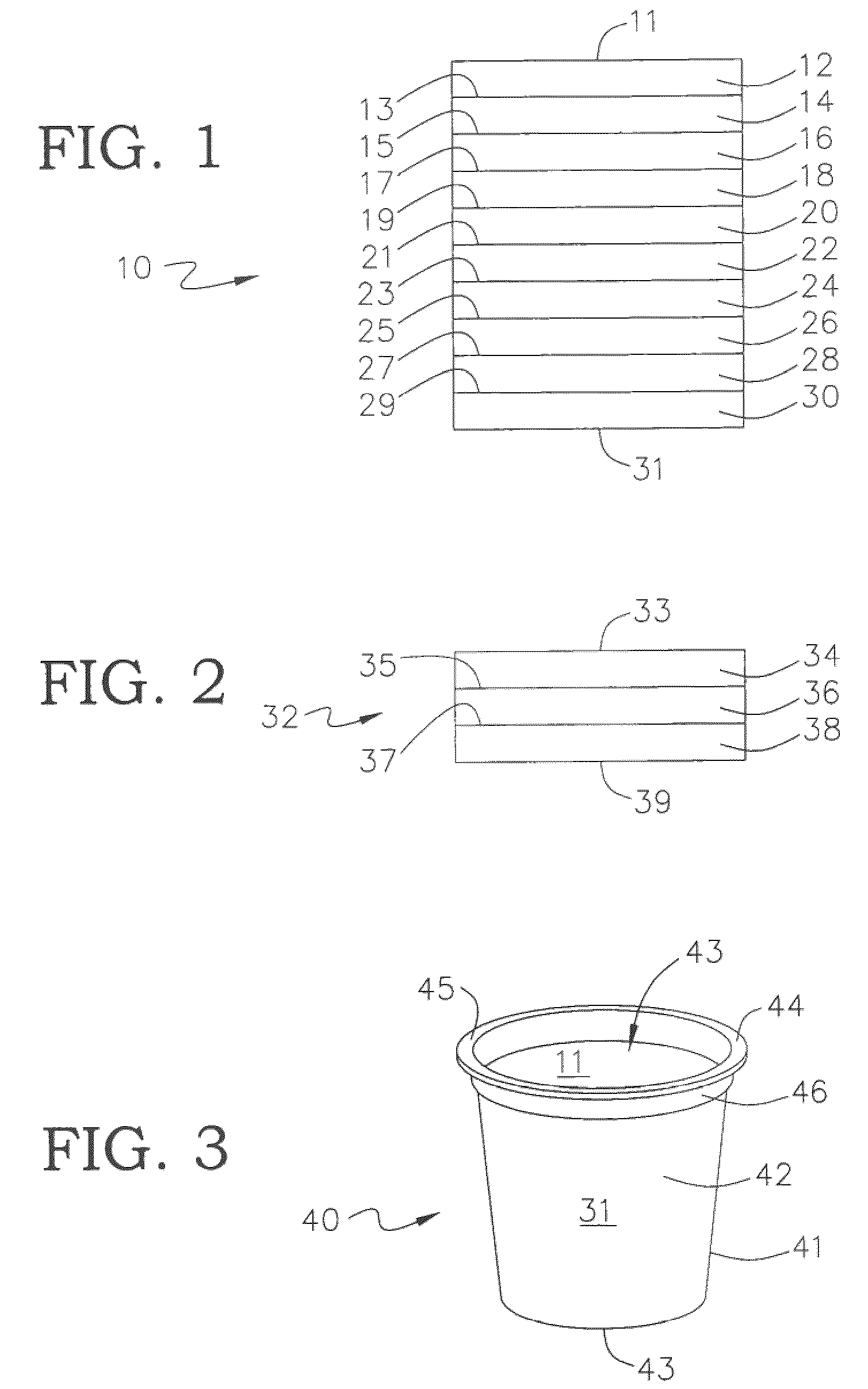
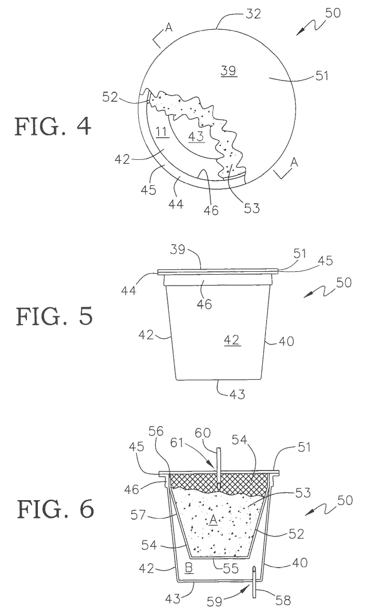
The present invention provides an improved container for brewing beverages that can be used as a single use processing cup. The container is made from a unitary multilayer polymeric sheet containing calcium carbonate, which forms a continuous sidewall portion integral with a bottom portion. The bottom portion and a top opening formed by a continuous perimeter flange located distally from the bottom portion form a cup with an interior surface layer, an exterior surface layer, and at least one intermediate layer. The container is designed to prevent the undesirable transmission of moisture or oxygen prior to use in a brewing process, while still permitting easy puncture for the introduction and removal of hot water for brewing to retain freshness and produce a flavorful brewed beverage. The container can also act as a carbon dioxide scavenger and is suitable for use in beverage making machines.

Problems solved by technology

These beverage making systems and containers such as the Keurig cup have been commercially successful however certain disadvantages have led to various attempts for improvements.
Furthermore due to the nature of the thermoforming process the container base is made from a sheet having a relatively uniform thickness and the thermoformed base bottom cannot easily be thinned without also thinning the base sidewall which adversely reduces the rigidity and strength of the base causing a tendency for the sidewall to buckle inward during the piercing process.
Also, as the outlet tube is pressed against the base bottom for piercing to permit exit of brewed coffee, a similar buckling may occur.
These distortions of the container disadvantageously can result in leakage proximate the outlet tube causing the liquid to spray or coat parts of the apparatus or otherwise remain or locate to undesirable places rather than travel along the desired path to the inside of the drinking cup.
This leakage may produce customer dissatisfaction due to loss of product, as well as require additional maintenance to avoid unsanitary conditions or further equipment malfunction.
These tubes are expensive and may require periodic sharpening.
Another problem associated with distortion of the base by the piercing operation is that some brewed beverage may remain in the second chamber unable to exit due to the distortion proximate the outlet tube pierced opening causing an area within the base to be below the outlet tube opening.
This attempt suffers from the need to provide not only different containers or cartridges, but also a different beverage making apparatus since the outlet tubes must be introduced from a position that is located 180° from the present apparatus location.
Also, there are additional complications attendant to the brewing process since the distribution of ingredient and flow of the liquid are not as easily controlled to yield a uniform extraction from e.g. ground coffee.
It is believed that this system while addressing the piercing problem would tend to produce a channelling effect in transfer of the hot water across the coffee resulting in a need for containers made from more material, or which use additional coffee or a longer residence time to produce an equivalent amount of brewed coffee.
Additionally the exit tube would require a motive force in opposition to gravity to cause the brewed liquid to exit which is believed to lead to additional expense to create a positive or negative pressure sufficient to effect transport or alternatively necessitates use of additional water to displace the requisite amount of brewed coffee thereby creating a waste of water and additional disposal concerns and weight.
This tendency of the container side wall to buckle under the force exerted by the outlet tube as it pierces or attempts to pierce the container bottom sometimes results in a failure of the outlet tube to achieve the desired penetration, thereby causing a malfunction in the brewing process which prevents delivery of some or all of the brewed beverage to the underlying drinking cup.
As previously mentioned, buckling of the container side wall can also distort the punctured opening in the container bottom, thereby disrupting a continuous seal about the tube perimeter which may result in leakage of the brewed beverage.
Other known problems include reliably sealing the flange or rim of the filter component to the interior side wall of the container, as well as in centrally securing the bottom of the filter component to the container bottom.
Failure to achieve a proper flange seal can cause the unsealed portion of the filter to collapse under pressure from introduction of the liquid, resulting in the brewed beverage being contaminated by beverage ingredient particles such as coffee grounds from the collapsed filter.
Contamination of the beverage may also happen if the filter bottom is not properly located and secured, resulting in the filter being punctured by the outlet probe as it projects upwardly through the container bottom.
Contamination also may occur by bursting of a filter element due to the pressure from the heated liquid being infused with the beverage ingredient(s).
Another problem arises from heat sealing the upper rim of the filter at or closely adjacent to the upper rim of the container side wall.
This increases the unoccupied head space between the outside of the filter and the surrounding container wall, and also limits the maximum amount of beverage medium that can be stored in the cartridge to that which can be contained within the filter.
In some cases, this can compromise the “strength” or extent of extraction of a resulting brewed beverage.
Beverage strength can be increased by filling the filter to its maximum capacity, but this can result in errant granules of the beverage medium spilling onto the container rim.
This in turn can disrupt the integrity of the seal between the cover and the container rim.
One approach to provide a material that is more easily pierced is to thin the wall of the container however this tends to undesirably decrease rigidity of the container and increase flexibility.
Such fluting may also introduce manufacturing complications by causing thinning of the barrier layers and materials within the container walls which assist the container in preventing or diminishing the permeability thereof to gases such as oxygen which have a deleterious effect on ingredients.
In addition, production of fluted containers may reduce production speeds.
Thus, there are several known drawbacks including difficulties associated with piercing or puncturing the container base, lack of rigidity or excessive flexibility in the base and the amount of packaging material required to produce a functional container.
Containers such as a Keurig cup or cartridge require tight size tolerances with a small range of variation to maintain acceptable levels of performance and these tight tolerances lead to waste in thermoforming operations.

Method used


Image

  • Mineral composite beverage brewing cup and cartridge
  • Mineral composite beverage brewing cup and cartridge
  • Mineral composite beverage brewing cup and cartridge

Examples


examples

[0097]Experimental results and reported properties of the following examples and comparative examples are based on the following test methods or substantially similar methods, unless otherwise noted:

[0098]Density: ASTM D-792

[0099]Tensile Strength: ASTM D-882, Method A

[0100]Oxygen Gas Transmission Rate (O2GTR): ASTM D-3985-81

[0101]Water Vapor Transmission Rate (WVTR): ASTM F 1249-90

[0102]Melt Index: ASTM D-1238, Condition E (190° C. / 2.16 kg) unless indicated otherwise herein e.g. propene-based (>50% C3 content) polymers tested at Condition TL (230° C.); polystyrene polymers were tested at 200° C.; 5 kg)

[0103]Melting point: ASTM D-3418, DSC with 5° C. / min heating rate

[0104]Vicat Softening Temperature: ASTM D-1525

[0105]Following are comparative examples and examples given to illustrate embodiments of the invention. All percentages are by weight unless indicated otherwise. All averages are mean unless indicated otherwise.

examples 1-10

[0106]Example 1 is a comparative example (not of the invention) and examples 2-10 are of the invention with examples 8-10 being illustrative hypotheticals. The following comparative example 1 is a prior art rigid single serve, disposable cup suitable for processing beverages therein such as those used in making a filter cartridge for brewing coffee in a Keurig-style coffee brewer. Examples 2-10 are of the invention and illustrate improvements afforded by preferred embodiments of the invention relative to this comparative example. The cups are made by thermally laminating together a seven layer blown film after slitting the tube to make a sheet with a three layer cast sheet by means known in the art to produce a ten layer sheet suitable for thermoforming by known techniques and equipment into a flanged cup.

[0107]The seven layer film may be made using conventional blown film equipment and procedures known in the art to produce the structure related below. The layers are all coextruded...


PUM


Abstract

A beverage filter cartridge having a cup, a filter, a lid and at least one beverage ingredient is provided where the cup and lid are sealed together to form an interior chamber which is separated into a first and second compartments by the filter, which is preferably basket or cone shaped, and a beverage ingredient such as coffee is contained inside first compartment, and at least one of the cup, lid and filter contains calcium carbonate in an amount effective to either improve the ability of beverage makers to pierce the cup or to provide a means for the cartridge to absorb CO2 emitted by the ingredient thereby reducing the hold time to packing and reducing the number of defective cartridges.

Description

TECHNICAL FIELD[0001]The present disclosure relates to improvements in the art of disposable beverage brewing containers such as disposable single serve beverage filter cartridges.BACKGROUND[0002]Beverage making systems are known where a predetermined amount of a beverage making ingredient, such as ground, freeze dried, or instant coffee, is held in a container or capsule, with or without filtration means, and then placed into a beverage making apparatus. The apparatus then introduces water into the container, where it dissolves, extracts, emulsifies, or dilutes the ingredient(s) to form a beverage. In a typical example, heated water is injected into a container having ground roast coffee in a filter cartridge which infuses the water to form brewed coffee. The beverage exits the container chamber e.g. by flowing through an opening or perforation in the container.[0003]Various beverage making systems and containers therefor are shown in U.S. Pat. No. 5,325,765 (Sylvan et al); U.S. Pa...

Claims


Application Information

Patent Timeline
Patent Type & Authority Patents(United States)
IPC IPC(8): A47J31/06
CPCA47J31/0673B65D85/8043B65D85/8061
Inventor KILBER, STEPHEN MARKWUEST, SAM EDWARDMELBYE, MICHAEL HOLMES
Owner BEMIS COMPANY INC
Learn More