Liquid seal assembly for a rotating torque tube

a technology of rotating torque and liquid seals, which is applied in the direction of surgical forceps, catheters, applications, etc., can solve the problems of blood flow becoming unstable, health risks, and devices that do not employ guidewires, and achieve the effect of effectively preventing vacuum loss

Inactive Publication Date: 2013-07-02
BOSTON SCI LTD
View PDF20 Cites 39 Cited by
  • Summary
  • Abstract
  • Description
  • Claims
  • Application Information

AI Technical Summary

Benefits of technology

[0014]A sealing assembly is provided that uses a liquid as a sealing medium as well as a lubricant of moveable catheter components. In one particular embodiment, the sealing assembly forms an effective seal around a rotatable torque tube as it enters into an area of high vacuum, while effectively preventing loss of vacuum at the proximal end of the sealing assembly. The sealing assembly includes a liner wrapped around a rotatable torque tube. The liner extends longitudinally along at least a portion of the torque tube. A flood space is formed within the inside diameter of the liner, including any internal clearance areas, lumens or gaps in or around the torque tube. A housing, i.e. “sealing member”, is also provided with an infusion port for infusing a sufficient amount of liquid in the flood space to create a seal around the torque tube. In one embodiment, a suction port is included in the

Problems solved by technology

As a result of accumulated obstructions, blood flow becomes restricted or blocked, creating health risks, including coronary artery disease, angina and heart attacks.
However, devices that do not employ guidewires are also possible.
Furthermore, findings have shown that stent deployment to treat Acute Coronary Sydrome (“ACS”) is often associated with plaque embolization in patients with ACS.
This heart damage increases the risk of long-term adverse clinical outcomes.
In another example, kidneys are known to be very susceptible to blockage if embolisms occur in a renal artery during renal interventions.
In the case of treatment of deep vein thrombosis, complications also occur if a clot breaks off and travels in the bloodstream to the lungs.
However, filter systems may allow small particles to pass and may be poorly positioned against a vessel wall.
Regardless of the particular application, problems which must be overcome to establish a fluid-tight seal are particularly difficult when the seal is required between components that move relative to each other.
In practice, a connector of catheter components and associated joints

Method used


Image

  • Liquid seal assembly for a rotating torque tube
  • Liquid seal assembly for a rotating torque tube
  • Liquid seal assembly for a rotating torque tube

Examples


Embodiment Construction

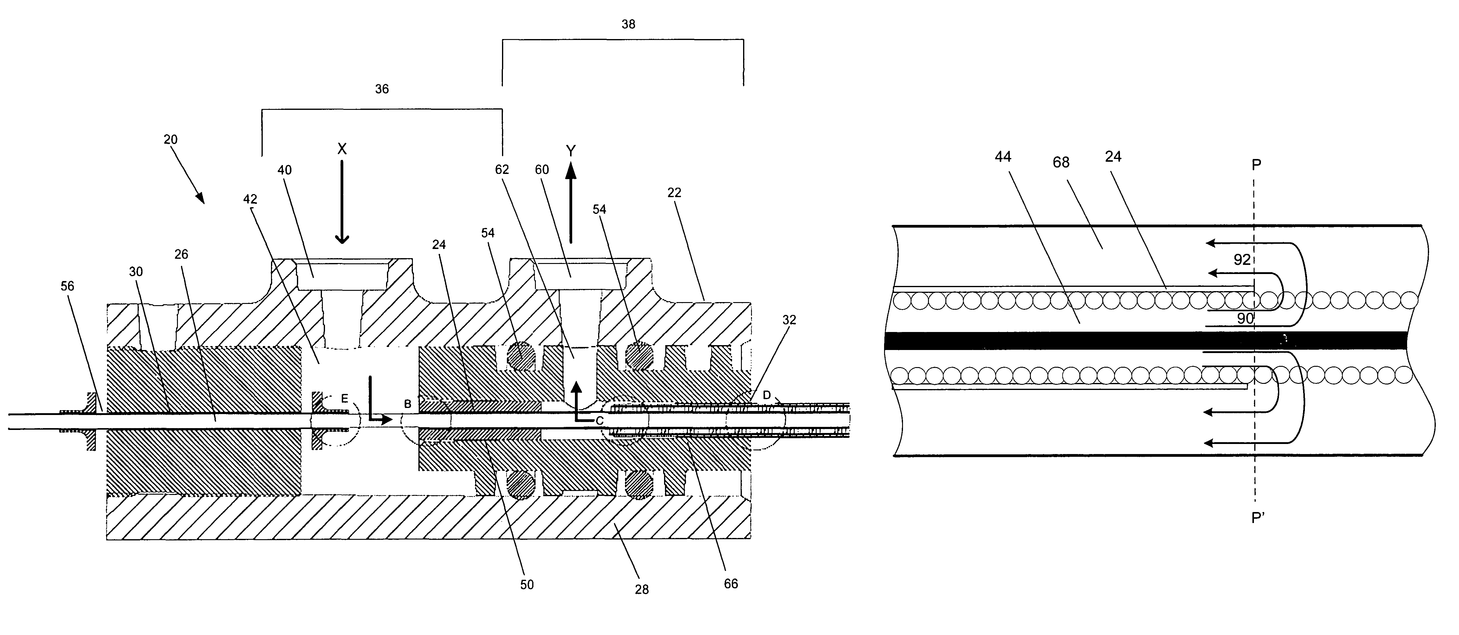
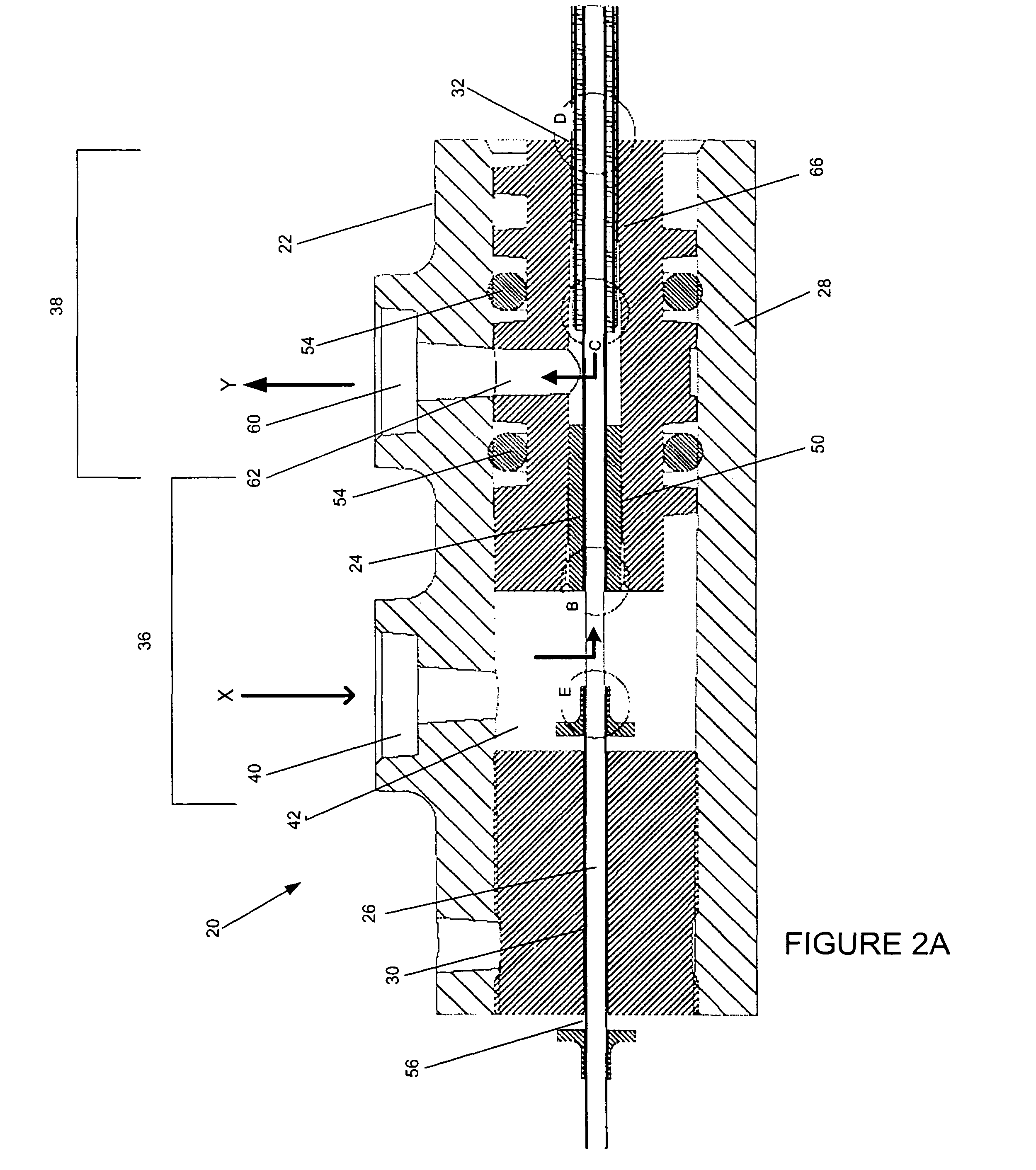
[0022]A sealing assembly is provided to hinder air or other fluid from seeping between various components of a medical device. In one aspect of the sealing assembly, a liquid seal site prevents air from traveling along a torque tube, such as down a drive shaft of a catheter system. A liner surrounds the torque tube and an infusion port permits a sealing liquid to immerse a flood space within the inside diameter of the liner, i.e. between the liner and the torque tube and / or within the torque tube, thereby creating a liquid seal around the torque tube. In one embodiment of the sealing assembly, an aspiration port is provided to force suction into a lumen extending along the length of the medical device in a distal direction. The liquid seal prevents diluting of the suction pressure by stopping ingress of air.

[0023]With this sealing assembly, a high tolerance seal is not required for the torque tube and there is no significant friction added. Thus, the clearances of the seal of the pr...


PUM


Abstract

A sealing assembly hinders or prevents air or other fluid from seeping between various components of a medical device by use of a liquid seal. An infusion port is for introducing a sealing liquid to immerse a flood space between a liner that surrounds a torque tube and/or within the torque tube, thereby creating a liquid seal around the torque tube and lubricating the torque tube. The length of the liner and the cross sectional space of the flood space are adjusted to control flow rate. An aspiration port may force suction pressure into a lumen extending along the length of the medical device in a distal direction. The liquid seal also prevents diluting of the suction pressure by stopping ingress of air.

Description

[0001]This application claims priority from U.S. Provisional Patent Application No. 60 / 453,846, filed Mar. 10, 2003 and is a continuation-in-part of U.S. patent application Ser. No. 09 / 826,487, filed Apr. 4, 2001, now U.S. Pat. No. 6,818,001. The disclosures of these applications are incorporated herein by reference in their entireties.FIELD OF THE INVENTION[0002]The present invention relates to an assembly for sealing structural elements that move relative to each other. The present invention is particularly, but not exclusively, useful for establishing a liquid seal around a rotatable torque tube in a medical device. It is to be understood that the terms “medical field” and “medical device”, as used herein, include traditional medicine as well as alternative medicines including chiropractic, acupuncture, etc., as well as the veterinary field.BACKGROUND OF THE INVENTION[0003]In numerous applications of devices in the medical field, it may be necessary or desirable to create a fluid...

Claims


Application Information

Patent Timeline
IPC IPC(8): A61B17/32A61B17/3207A61B1/01A61B8/12A61B17/00A61B17/22A61B17/28A61B17/34A61M1/00A61M39/06
CPCA61B5/061A61B5/415A61B5/418A61B8/4209A61B17/320725A61B17/320758A61M39/06A61B1/00137A61B1/01A61B8/12A61B17/32002A61B17/3462A61B2017/00017A61B2017/00199A61B2017/00973A61B2017/22049A61B2017/2927A61B2017/320032A61B2217/005A61M1/0058A61M1/008A61M1/0084A61M39/0606A61M1/85A61M1/84A61M1/77
Inventor WULFMAN, EDWARD I.TORRANCE, CASEY
Owner BOSTON SCI LTD
Why Eureka
Try Eureka