Method of removing and solidifying carbon dioxide from a fluid stream and fluid separation assembly

a technology of carbon dioxide and fluid stream, applied in the direction of sedimentation settling tank, lighting and heating apparatus, separation process, etc., can solve the problems of high cost and complex use of such methods for removing carbon dioxide from fluid stream

Active Publication Date: 2013-07-02
TWISTER BV
View PDF8 Cites 21 Cited by
  • Summary
  • Abstract
  • Description
  • Claims
  • Application Information

AI Technical Summary

Problems solved by technology

The use of such methods for removing carbon dioxide from a fluid stream is extremely complex and expensive.

Method used


Image

  • Method of removing and solidifying carbon dioxide from a fluid stream and fluid separation assembly
  • Method of removing and solidifying carbon dioxide from a fluid stream and fluid separation assembly
  • Method of removing and solidifying carbon dioxide from a fluid stream and fluid separation assembly

Examples


Embodiment Construction

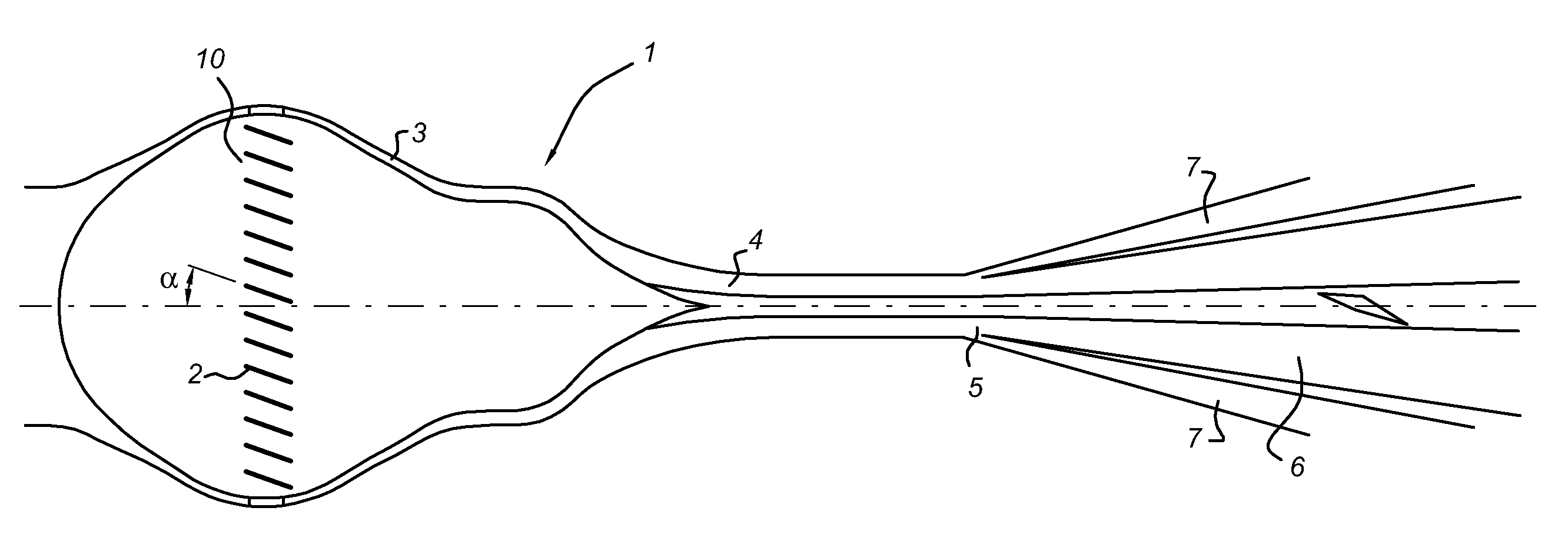
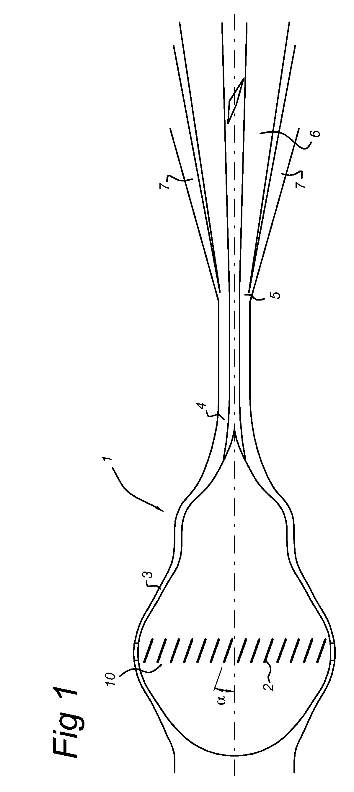
[0033]FIG. 1 schematically depicts a longitudinal sectional view of a cyclonic fluid separator 1 that may be used in embodiments of the invention. Such a cyclonic fluid separator is described in more detail in international patent application WO03 / 029739. It must be understood that, in embodiments of the invention, also cyclonic fluid separators of a different type may be used, e.g. a cyclonic fluid separator as described in WO99 / 01194, WO2006 / 070019 and WO00 / 23757.

[0034]The cyclonic fluid separator 1 comprises a converging fluid inlet section 3, a diverging fluid outlet section 5 and a tubular throat portion 4 arranged in between the converging fluid inlet section 3 and diverging fluid outlet section 5. The cyclonic fluid separator 1 further comprises a swirl creating device, e.g. a number of swirl imparting vanes 2, configured to create a swirling motion of the fluid within at least part of the cyclonic fluid separator 1.

[0035]The converging fluid inlet section 3 comprises a first...


PUM

PropertyMeasurementUnit
mole percentageaaaaaaaaaa
temperatureaaaaaaaaaa
timeaaaaaaaaaa

Abstract

The invention relates to a method of removing carbon dioxide from a fluid stream by a fluid separation assembly. The fluid separation assembly has a cyclonic fluid separator with a tubular throat portion arranged between a converging fluid inlet section and a diverging fluid outlet section and a swirl creating device. The separation vessel has a tubular section positioned on and in connection with a collecting tank. In the method, a fluid stream with carbon dioxide is provided. Subsequently, a swirling motion is imparted to the fluid stream so as to induce outward movement. The swirling fluid stream is then expanded such that components of carbon dioxide in a meta-stable state within the fluid stream are formed. Subsequently, the outward fluid stream with the components of carbon dioxide is extracted from the cyclonic fluid separator and provided as a mixture to the separation vessel. The mixture is then guided through the tubular section towards the collecting tank while providing processing conditions such that solid carbon dioxide is formed. Finally, solidified carbon dioxide is extracted.

Description

FIELD OF THE INVENTION[0001]The invention relates to a method of removing carbon dioxide from a fluid stream. In particular, embodiments of the present invention relate to a method of removing carbon dioxide from a natural gas stream. The invention further relates to a fluid separation assembly.BACKGROUND OF THE INVENTION[0002]Natural gas from storage or production reservoirs typically contains carbon dioxide (CO2). Such a natural gas is denoted as a “sour” gas. Another species denoted as “sour” in a fluid stream is hydrogen sulphide (H2S). A fluid stream without any of aforementioned sour species is denoted as a “sweet” fluid.[0003]CO2 promotes corrosion within pipelines. Furthermore, in some jurisdictions, legal and commercial requirements with respect to a maximum concentration of CO2 in a fluid stream may be in force. Therefore, it is desirable to remove CO2 from a sour fluid stream.[0004]Fluid sweetening processes, i.e. a process to remove a sour species like carbon dioxide fro...

Claims


Application Information

Patent Timeline
Patent Type & Authority Patents(United States)
IPC IPC(8): B01D45/12C01B32/55
CPCB01D53/24C01B31/22C10L3/10C10L3/102C10L5/366F25J3/061F25J3/0635F25J3/064F25J3/067B01D21/02B01D2256/22B01D2257/504B01D2258/06F25J2205/10F25J2205/20F25J2215/04F25J2270/90Y02C10/12C01B32/55Y02C20/40Y02P20/151Y02P70/10
Inventor PRAST, BARTLANGERAK, JAKOB ARIE CORNELISBETTING, MARCOTJEENK WILLINK, CORNELIS ANTONIE
Owner TWISTER BV
Why Eureka
Try Eureka