Lithium microbattery and fabrication method thereof

a technology of lithium microbattery and fabrication method, which is applied in the field of lithium microbattery, can solve the problems of high cost, ineffectiveness, and high cost of lithium microbatteries, and achieves the effects of moderate electric resistance, long life and optimized energy storage efficiency

Active Publication Date: 2013-07-02
COMMISSARIAT A LENERGIE ATOMIQUE ET AUX ENERGIES ALTERNATIVES
View PDF10 Cites 7 Cited by
  • Summary
  • Abstract
  • Description
  • Claims
  • Application Information

AI Technical Summary

Benefits of technology

[0017]In particular, the object of the invention is to provide a high-performance lithium microbattery presenting an optimized energy storage efficiency, a moderate electric resistance and a long lifetime. The microbattery is designed to be fabricated by means of an industrial fabrication method that is easy to implement, economically viable and compatible with the technologies implemented in the microelectronics field.

Problems solved by technology

Lithium microbatteries are however very sensitive to air and in particular to moisture.
Generally not very efficient for masking microbatteries of small size, in particular of millimetric dimensions, mechanical masking also induces risks of particulate contamination and damage of the thin layer.
Implementation of this method is complex resulting in it not being able to meet the yield demands of industry.
Furthermore, this masking method also does not meet the dimensional specifications of the future generations of integrated circuits, and is consequently hardly suitable for application in the microelectronics field.
Although this microfabrication method enables the dimensional limits to be pushed back and the resolution of the patterns to be increased, it does however remain complex with the use of several layers of masks and of non-aqueous solutions which are sometimes incompatible with the active materials of the stack.
These shortcomings generally result in deterioration of the functional interfaces between the different layers constituting the stack.
This contact results in a decrease of the performances of the microbattery.
Other drawbacks affect the performances of dissymmetric microbatteries.
These repeated volume modifications rapidly lead to mechanical damage.

Method used


Image

  • Lithium microbattery and fabrication method thereof
  • Lithium microbattery and fabrication method thereof
  • Lithium microbattery and fabrication method thereof

Examples


example

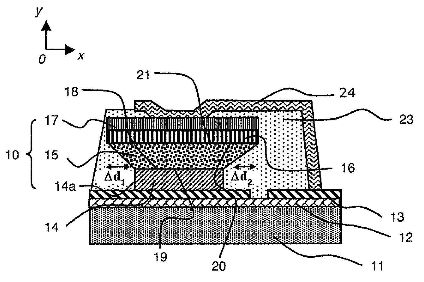
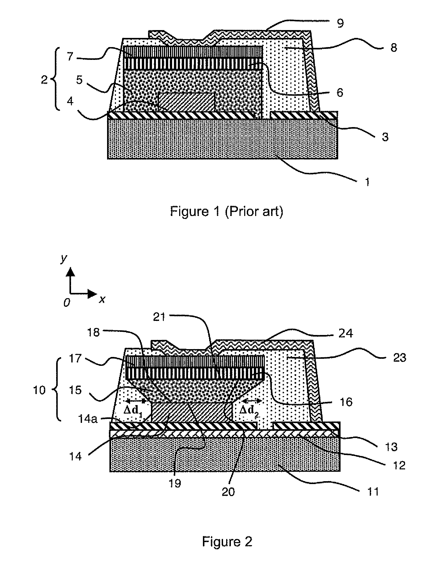
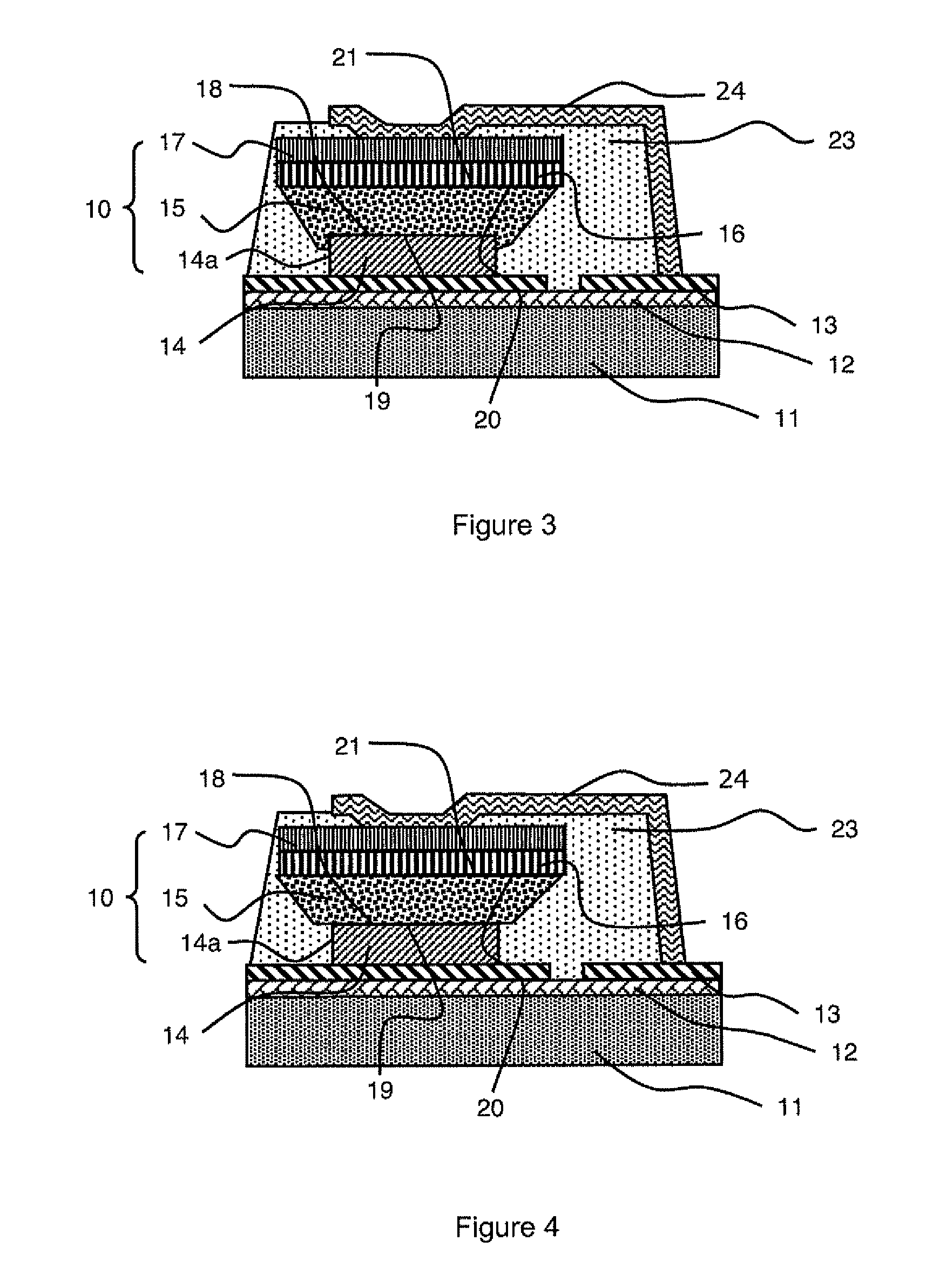
[0078]A lithium microbattery having an optimized architecture has been produced by means of the fabrication method of the invention. A stack 10 is obtained on a silicon substrate 11 with a SiO2+Si3N4 passivation bilayer 12. Current collector 13 is formed by deposition of a thin layer of tungsten with a thickness of 250 nm by photolithography followed by wet etching, by immersion in a Tungsten Etch® Bath marketed by Micropur Technic, for 2 minutes at 25° C. Full wafer deposition is then performed successively for formation of the following thin layers:[0079]LiV2O5 with a thickness of 1 μm forming first electrode 14,[0080]LiPON with a thickness of 1.5 μm forming solid electrolyte 15,[0081]Si with a thickness of 0.1 μm forming second electrode 16,[0082]Ti with a thickness of 0.25 μm forming current collector 17.

[0083]Simultaneous etching of current collector 17 and of Ti / Si second electrode 16 is then performed by reactive ion etching with a SF6 plasma in a reactive ion etching reactor...


PUM

PropertyMeasurementUnit
lengthaaaaaaaaaa
lengthaaaaaaaaaa
thicknessaaaaaaaaaa

Abstract

The microbattery is formed by a stack of solid thin layers on a substrate which, starting from the substrate, successively comprises a first electrode, a solid electrolyte and a second electrode / current collector assembly. A first surface and a second surface of the electrolyte are respectively in contact with a main surface of the first electrode and a main surface of the second electrode / current collector assembly. The dimensions of the main surface of the first electrode are smaller than the dimensions of the main surface of said assembly, and the dimensions of the first surface of the solid electrolyte are smaller than the dimensions of the second surface of the solid electrolyte. The solid electrolyte is furthermore not in contact with the substrate.

Description

BACKGROUND OF THE INVENTION[0001]The invention relates to a lithium microbattery formed by a stack of solid thin layers on a substrate. Starting from the substrate, the stack successively comprises a first electrode, a solid electrolyte and a second electrode / current collector assembly formed by at least one thin layer, a first surface and a second surface of the electrolyte being in contact respectively with a main surface of the first electrode and a main surface of the second electrode / current collector assembly. The main surfaces are facing one another and the dimensions of the main surface of the first electrode are smaller than the dimensions of the main surface of the assembly.[0002]The invention also relates to a fabrication method of such a microbattery.STATE OF THE ART[0003]Lithium microbatteries, also called “all-solid-state” batteries, are storage batteries which comprise two electrodes implementing lithium. Hybrid systems also exist which only comprise a single electrod...

Claims


Application Information

Patent Timeline
Patent Type & Authority Patents(United States)
IPC IPC(8): H01M6/18
CPCH01M6/18H01M6/186H01M6/187H01M6/40H01M10/052H01M10/0562H01M10/0585H01M10/0436Y02E60/122H01M2300/0068Y02E60/10Y02P70/50
Inventor OUKASSI, SAMISALOT, RAPHAELDUNOYER, NICOLASMARTIN, STEVE
Owner COMMISSARIAT A LENERGIE ATOMIQUE ET AUX ENERGIES ALTERNATIVES
Why Eureka
Try Eureka