Motor magnetic pole position correction method

a technology of magnetic pole position and direct drive motor, which is applied in the direction of motor/generator/converter stopper, electronic commutator, dynamo-electric converter control, etc., can solve the problems of torque decrease, mounting error between direct drive motors, and magnetic pole position correction methods discussed

Active Publication Date: 2013-07-02
OKUMA CORP
View PDF6 Cites 2 Cited by
  • Summary
  • Abstract
  • Description
  • Claims
  • Application Information

AI Technical Summary

Benefits of technology

[0040]More specifically, even in a case where a positional relationship between the direct drive motor and a detection origin of the position detector is not in the perfect state, a deviation caused between the actual position of the direct drive motor and a detection value of the position detector can be corrected by a control system. Further, accurate current phase control can be realized. Therefore, the present invention can eliminate any undesirable reduction in output torque when the deviation is caused. Further, even when the direct drive motor is brought into an uncontrollable state, the table cannot move beyond the limit of a predetermined movable range and does not cause any collision with a neighboring component.

Problems solved by technology

However, it is usual that a mounting error occurs between the direct drive motor 11 and the position detector 12 due to clearances provided for respective mounting holes and female screw holes, or as a result of mechanical errors in machining, such as positional deviations between the mounting holes and the female screw holes.
However, the multi-polar motor is disadvantageous in that the torque decreases greatly when the mounting error occurs.
Therefore, the magnetic pole position correction method discussed in JP 2000-166278 A is not applicable to a rotation axis whose movable angle is limited and a linear axis whose movable distance is limited.
Further, at an initial state, the positional relationship between the direct drive motor and the position detector may greatly deviate from an optimum magnetic pole position correction value due to a mistake or an error in a mounting operation of the direct drive motor and the position detector.
Further, the terminology “mounting error” is amounting angle error that may be caused due to the clearances provided for respective mounting holes and female screw holes, or by mechanical errors in machining, such as positional deviations between the mounting holes and the female screw holes.
If the deviation in the positional relationship between the direct drive motor and the position detector in the mounted state exceeds the limit of the ±90° range in terms of the electrical angle, the direct drive motor becomes uncontrollable.
In such a situation, the positioning of the motor will fail and the magnetic pole position correction cannot be performed.
Further, the table may move abnormally beyond the limit of an estimated movable range and may collide with a neighboring machine component and may ultimately be damaged.
Thus, the intended correction cannot be carried out thoroughly.
Thus, the correction cannot be carried out thoroughly.

Method used


Image

  • Motor magnetic pole position correction method
  • Motor magnetic pole position correction method
  • Motor magnetic pole position correction method

Examples


first embodiment

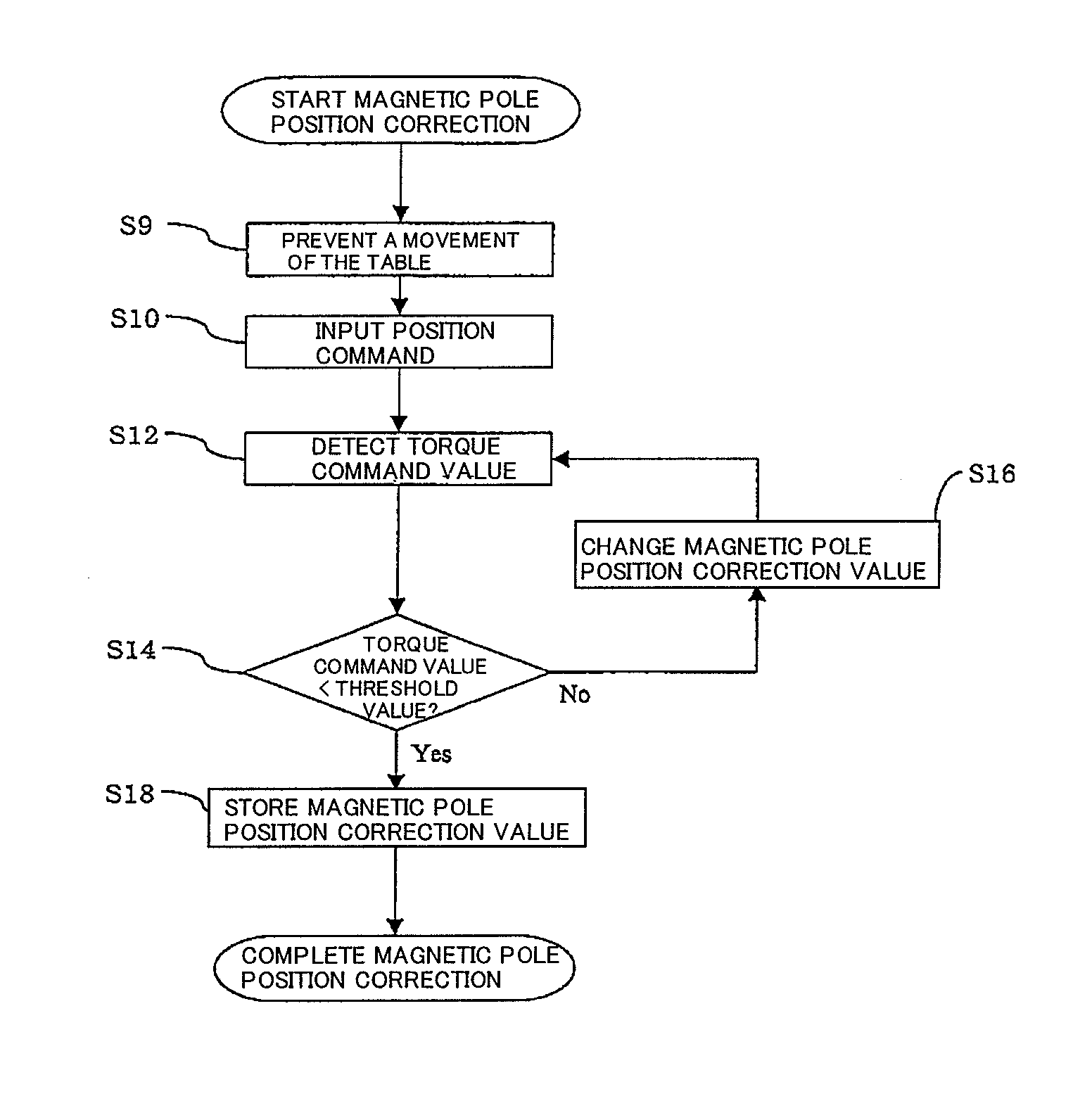
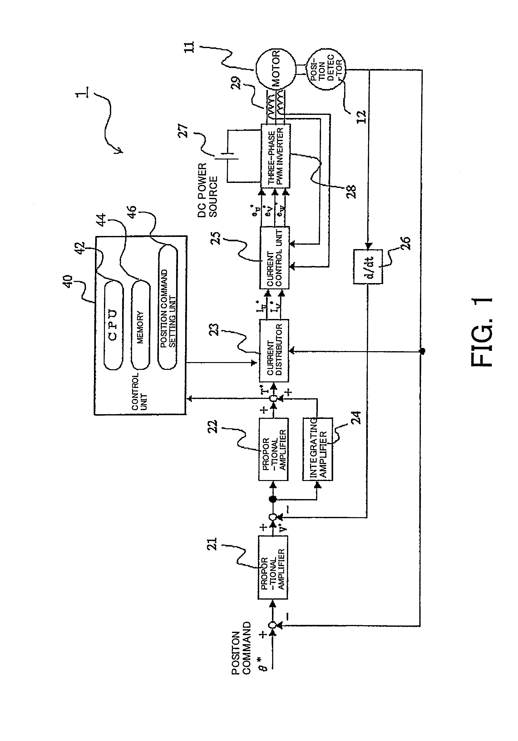
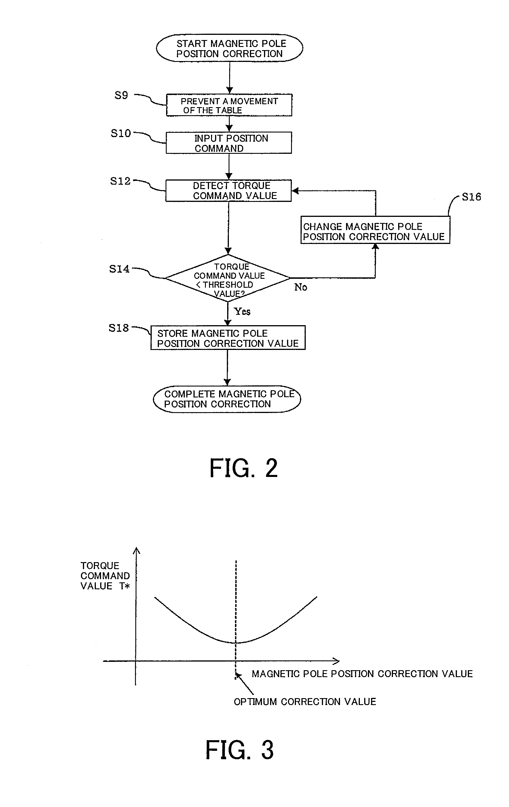
[0050]A first embodiment of the present invention is described below with reference to FIG. 1 to FIG. 3. FIG. 1 is a block diagram illustrating a schematic configuration of a motor control system 1 that can realize a motor magnetic pole position correction method according to an embodiment of the present invention. FIG. 2 is a flowchart illustrating a processing procedure of the motor magnetic pole position correction method according to the first embodiment of the present invention. FIG. 3 illustrates a relationship between magnetic pole position correction value and torque command value T* in a state where a direct drive motor outputs a constant thrust / torque.

[0051]The motor control system 1 illustrated in FIG. 1 includes a control unit 40, which includes a central processing unit (CPU) 42, a memory 44, and a position command setting unit 46. The central processing unit 42 is functionally operable to read a magnetic pole position correction program from memory 44 and execute the m...

second embodiment

[0069]FIG. 4 is a flowchart illustrating a processing procedure of a motor magnetic pole position correction method according to a second embodiment of the present invention. The method according to the second embodiment is advantageous in that an optimum magnetic pole position correction value can be obtained accurately, when compared to the first embodiment.

[0070]In the second embodiment, the memory 44 of the control unit 40 serves as a T*register that stores a magnetic pole position correction value and a torque command value. First, in steps S20 and S22, the control unit 40 initializes the magnetic pole position correction value and also initializes the T*register. In this case, the T*register stores a maximum torque command value that can be applied to the direct drive motor.

[0071]Next, in step S23, the control unit 40 prevents the movement of the table connected to the movable element using a mechanical brake. Subsequently, in step S24, the position command θ* having been set ...

third embodiment

[0081]FIG. 5 is a flowchart illustrating a processing procedure of a motor magnetic pole position correction method according to a third embodiment. The procedure of the magnetic pole position correction method according to the present embodiment is described below with reference to the flowchart illustrated in FIG. 5.

[0082]In the magnetic pole position correction method described in the first and second embodiments, if the torque command is set to be equal to or greater than a rated thrust / torque of the motor, the motor may be excessively heated during an adjustment operation and a thermal protector provided in the motor may forcibly stop the adjustment.

[0083]To prevent the above-described problem, it is useful to set a torque limit function to prevent the torque command value from exceeding a predetermined constant value. When the torque limit function is set appropriately to hold the torque command to be equal to or less than the rated thrust / torque of the motor, the motor temper...


PUM


Abstract

A motor magnetic pole position correction method includes preventing a movement of a movable element of a direct drive motor by mechanical brake (step S9), generating a command that designates a position spaced or separated from the present position (step S10), detecting a torque command value of the direct drive motor (step S12), determining a magnetic pole position correction value based on a comparison between the detected torque command value and a predetermined threshold value (steps S14 and S16), storing the determined magnetic pole position correction value in a memory (step S18), and performing motor control using an electrical angle offset value obtained based on the magnetic pole position correction value stored in the memory.

Description

PRIORITY INFORMATION[0001]This application claims priority to Japanese Patent Application No. 2010-261890, filed on Nov. 25, 2010, which is incorporated herein by reference in its entirety.BACKGROUND[0002]1. Technical Field[0003]The present invention relates to a linear type direct drive motor or a rotary type direct drive motor, which can be used to table of a machine tool. The present invention relates to a technique capable of preventing the output torque from decreasing when a mounting error occurs between a motor and a position detector.[0004]2. Related Art[0005]Direct drive motors are usable to realize high-speed and high-accurate positioning of the table of a machine tool when a motor is used to drive a table directly without using any ball screw or any speed reduction device.[0006]When the motor is a direct drive type, the positioning accuracy of the motor directly influences the positioning accuracy of the table because of non-presence of a speed reduction mechanism. Theref...

Claims


Application Information

Patent Timeline
Patent Type & Authority Patents(United States)
IPC IPC(8): H02P6/16H02P6/00H02P6/06H02P6/08H02P6/17H02P6/28H02P21/00H02P21/22H02P23/16H02P23/18H02P25/026H02P27/04H02P27/08
CPCH02P6/142H02P6/181H02P6/15
Inventor KAWAI, YOICHI
Owner OKUMA CORP
Why Eureka
Try Eureka