Constant current circuit start-up circuitry for preventing power input oscillation

a technology of constant current circuit and start-up circuit, which is applied in the direction of electric variable regulation, process and machine control, instruments, etc., can solve the problems of not being suitable for lower current consumption, and achieve the effect of reliable start-up of constant current circuit in a short period of time and low current consumption operation

Active Publication Date: 2013-07-02
ABLIC INC
View PDF9 Cites 0 Cited by
  • Summary
  • Abstract
  • Description
  • Claims
  • Application Information

AI Technical Summary

Benefits of technology

[0015]The constant current circuit according to the present invention provides the following effect. Until a node A reaches a start-up state, an excitation current is continued to be supplied to a node B, to thereby reliably start up the constant current circuit in a short period of time without repeating the start-up state and a zero steady state.
[0016]Besides, the following effect is also provided. When a potential of the node A falls below a threshold of the start-up circuit because of disturbance such as power supply fluctuations, the excitation current is supplied again to re-start up the constant current circuit, to thereby prevent the constant current circuit from shifting to the zero steady state.
[0017]Further, the start-up circuit has an inverter configuration, and hence a steady current does not continue to flow before and after the start-up, which is still another effect of being suitable for low current consumption operation.

Problems solved by technology

Achieving lower current consumption operation is also an important issue for the constant current circuit.
This leads to a fear that the constant current circuit repeats the start-up state and the zero steady state to enter an oscillating state.
Further, after the start-up of the constant current circuit, a current flows through the determination circuit section 411 all the time, which is not suitable for lower current consumption.

Method used


Image

  • Constant current circuit start-up circuitry for preventing power input oscillation
  • Constant current circuit start-up circuitry for preventing power input oscillation
  • Constant current circuit start-up circuitry for preventing power input oscillation

Examples


first embodiment

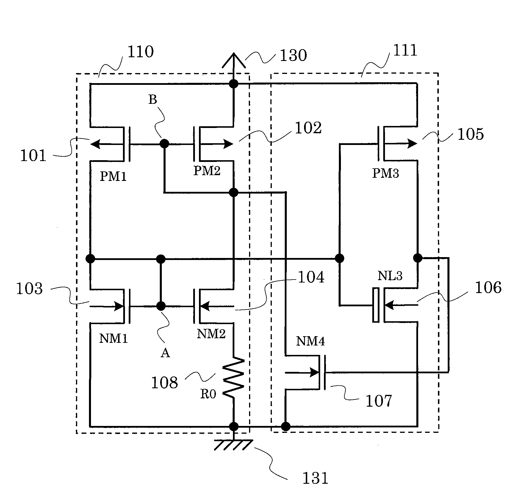
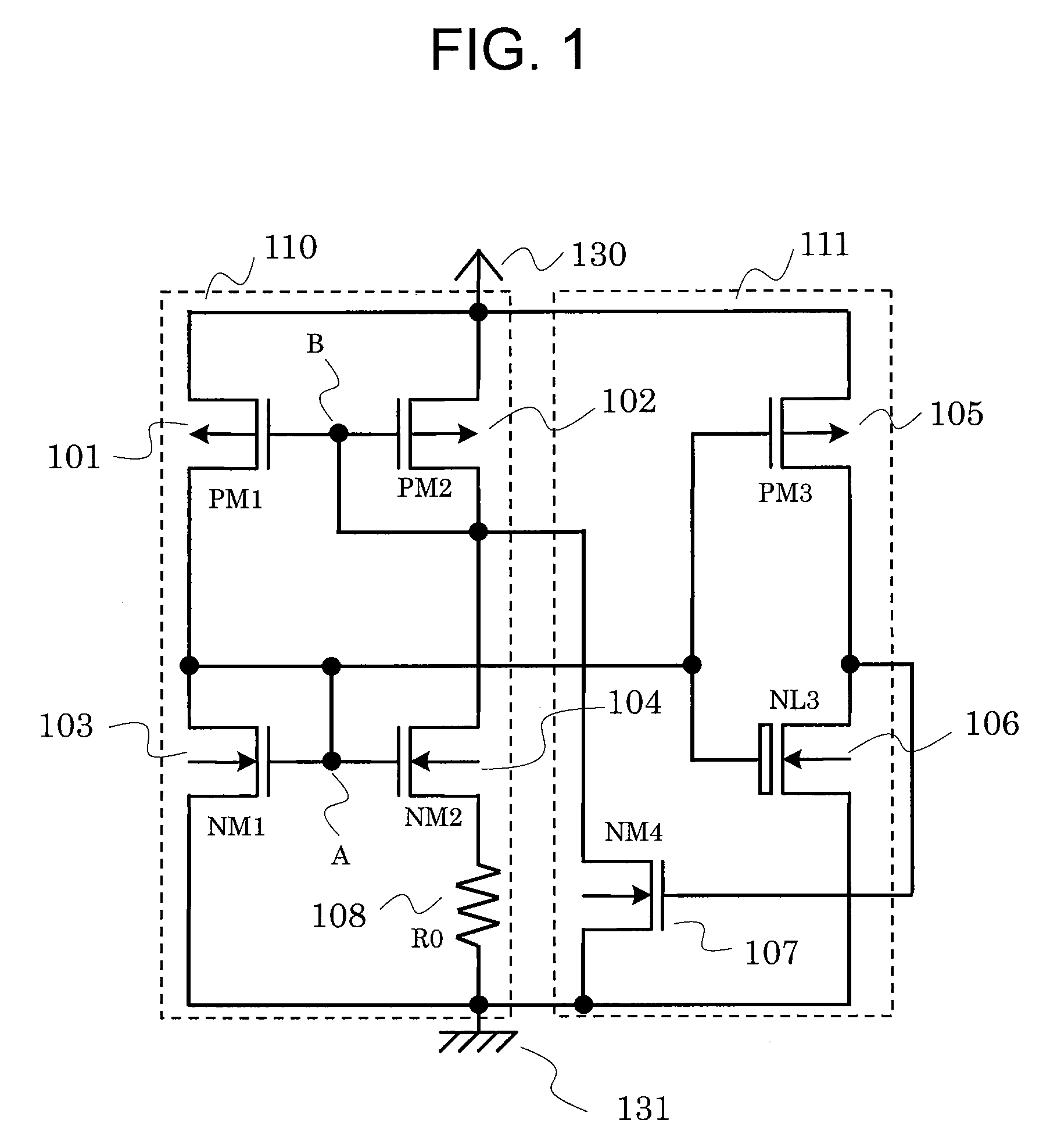
[0025]FIG. 1 is a circuit diagram of a constant current circuit according to a first embodiment of the present invention.

[0026]The constant current circuit according to the first embodiment includes a constant current circuit section 110 and a start-up circuit section 111.

[0027]The constant current circuit section 110 includes a P-channel transistor 101, a P-channel transistor 102, an N-channel transistor 103, an N-channel transistor 104, and a resistor 108. The P-channel transistor 101 has a source connected to a power supply terminal 130, a drain connected to a drain of the N-channel transistor 103, and a gate connected to a gate of the P-channel transistor 102. The P-channel transistor 102 has a source connected to the power supply terminal 130, and a drain connected to its own gate and a drain of the N-channel transistor 104. The N-channel transistor 103 has a source connected to a ground terminal 131, and the drain connected to its own gate and a gate of the N-channel transisto...

second embodiment

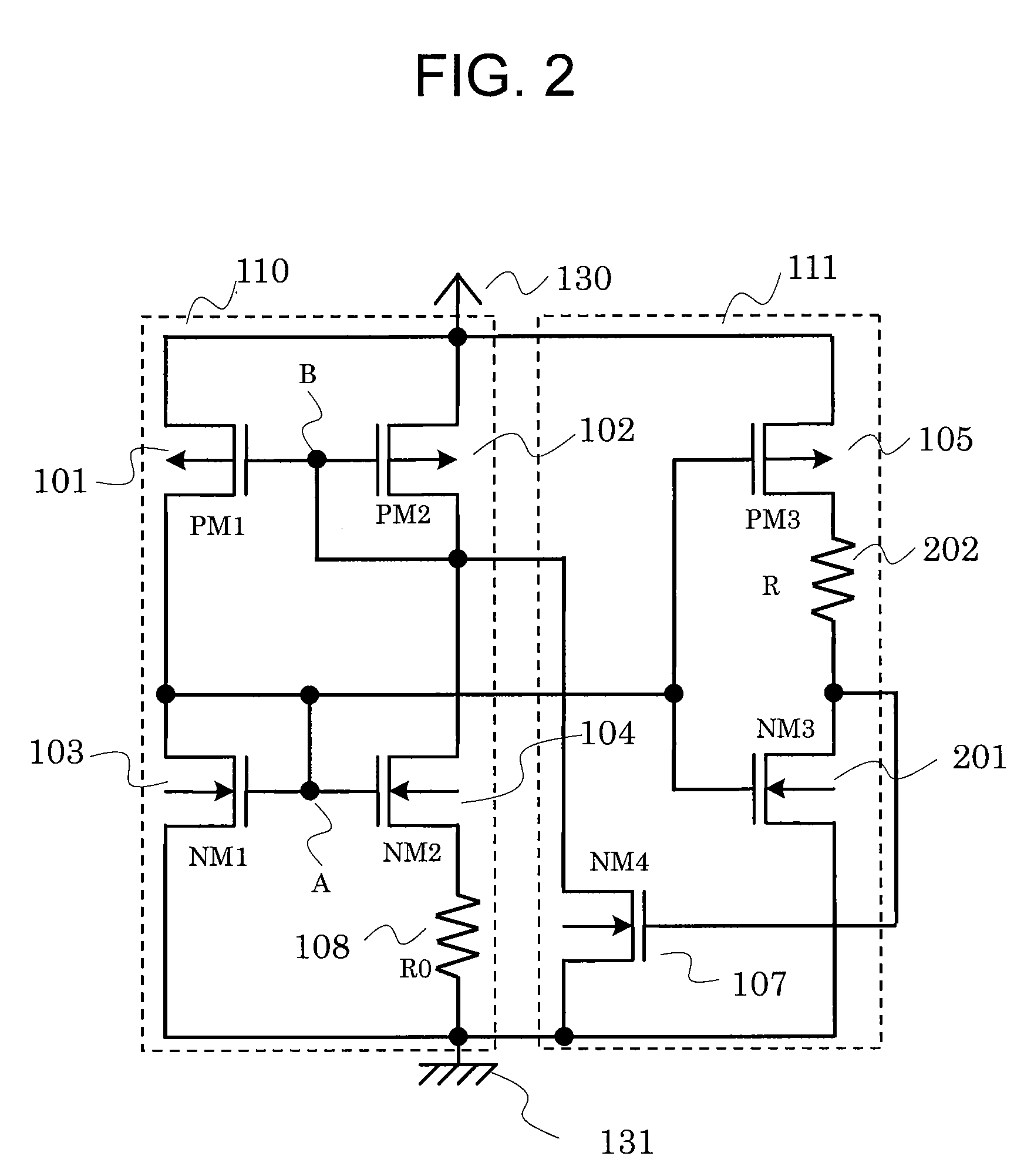
[0037]FIG. 2 is a circuit diagram of a constant current circuit according to a second embodiment of the present invention.

[0038]FIG. 2 is different from FIG. 1 in that a resistor 202 is interposed between an N-channel transistor 201 and the P-channel transistor 105, and that the N-channel transistor 201 has the same threshold as the N-channel transistor 103 and the N-channel transistor 104.

[0039]The resistor 202 has one end connected to the drain of the P-channel transistor 105 and another end connected to a drain of the N-channel transistor 201 and the gate of the N-channel transistor 107.

[0040]Next, an operation of the constant current circuit according to the second embodiment is described.

[0041]Even in a case where the N-channel transistor 201 cannot employ a transistor different in threshold from the N-channel transistor 103 and the N-channel transistor 104 due to restrictions on manufacturing process or the like, it is possible to make adjustment by the resistor 202. By adding...

third embodiment

[0043]FIG. 3 is a circuit diagram of a constant current circuit according to a third embodiment of the present invention.

[0044]FIG. 3 is different from FIG. 1 in that a resistor 301 is interposed between the N-channel transistor 107 and the P-channel transistor 102.

[0045]The resistor 301 has one end connected to the gate of the P-channel transistor 102 and another end connected to the drain of the N-channel transistor 107.

[0046]Next, an operation of the constant current circuit according to the third embodiment is described.

[0047]When the resistor 301 is not interposed, the excitation current by the N-channel transistor 107 is determined as {VDD−Vth(PM2)} / Ron(NM4), where VDD is the power supply voltage, Vth(PM2) is the threshold of the P-channel transistor 102, and Ron(NM4) is an ON-state resistance of the N-channel transistor 107. As apparent from the expression, as the power supply voltage becomes larger, a value of the excitation current increases, resulting in increased current ...


PUM


Abstract

Provided is a constant current circuit capable of low current consumption operation, which is prevented from repeating a start-up state and a zero steady state and entering an oscillating state when power is activated. When power is activated, until a node (A) reaches a start-up state, an excitation current is continued to be supplied to a node (B), to thereby reliably start up the constant current circuit in a short period of time without repeating the start-up state and the zero steady state.

Description

RELATED APPLICATIONS[0001]This application claims priority under 35 U.S.C. §119 to Japanese Patent Application No. 2009-273646 filed on Dec. 1, 2009, the entire content of which is hereby incorporated by reference.BACKGROUND OF THE INVENTION[0002]1. Field of the Invention[0003]The present invention relates to a constant current circuit to be formed on a chip of a semiconductor integrated circuit, and more particularly, to a constant current circuit including start-up means for preventing oscillation when power is input.[0004]2. Description of the Related Art[0005]Constant current circuits are used as current sources for circuits in various types of electronic devices. It is a function of the constant current circuit to output a constant current to an output terminal independently of power supply fluctuations at a power supply terminal. Achieving lower current consumption operation is also an important issue for the constant current circuit.[0006]FIG. 4 illustrates a circuit diagram ...

Claims


Application Information

Patent Timeline
Patent Type & Authority Patents(United States)
IPC IPC(8): G05F3/16
CPCG05F3/242
Inventor HIKICHI, TOMOKIARIYAMA, MINORUMURAOKA, DAISUKEFUJIMURA, MANABU
Owner ABLIC INC
Why Eureka
Try Eureka