Beam Scanning Methods for Improved Eye Safety in LiDAR Systems

a beam scanning and lidar technology, applied in the field of lidar (light detection and ranging) systems, can solve problems such as increasing the risk of laser exposure in the scen

Pending Publication Date: 2020-04-30
CHARLES STARK DRAPER LABORATORY
View PDF1 Cites 0 Cited by
  • Summary
  • Abstract
  • Description
  • Claims
  • Application Information

AI Technical Summary

Benefits of technology

[0004]Embodiments of the present invention are directed to a LiDAR system with a field of view that use selective scanning to address the issue of eye safety when using a LiDAR system which emit one or more laser beams. The LiDAR system includes a laser, an array of optical emitters, an objective lens optically coupling each optical emitter of the array of optical emitters to a respective unique portion of the field of view, an optical switching ...

Problems solved by technology

However, multiple beams increase ...

Method used


Image

  • Beam Scanning Methods for Improved Eye Safety in LiDAR Systems
  • Beam Scanning Methods for Improved Eye Safety in LiDAR Systems
  • Beam Scanning Methods for Improved Eye Safety in LiDAR Systems

Examples


Embodiment Construction

[0022]Various embodiments of the present invention are directed to a LiDAR system that dynamically varies a temporal pattern for routing light from a laser through an optical switching network to a sequence of optical emitters while avoiding potential eye injury.

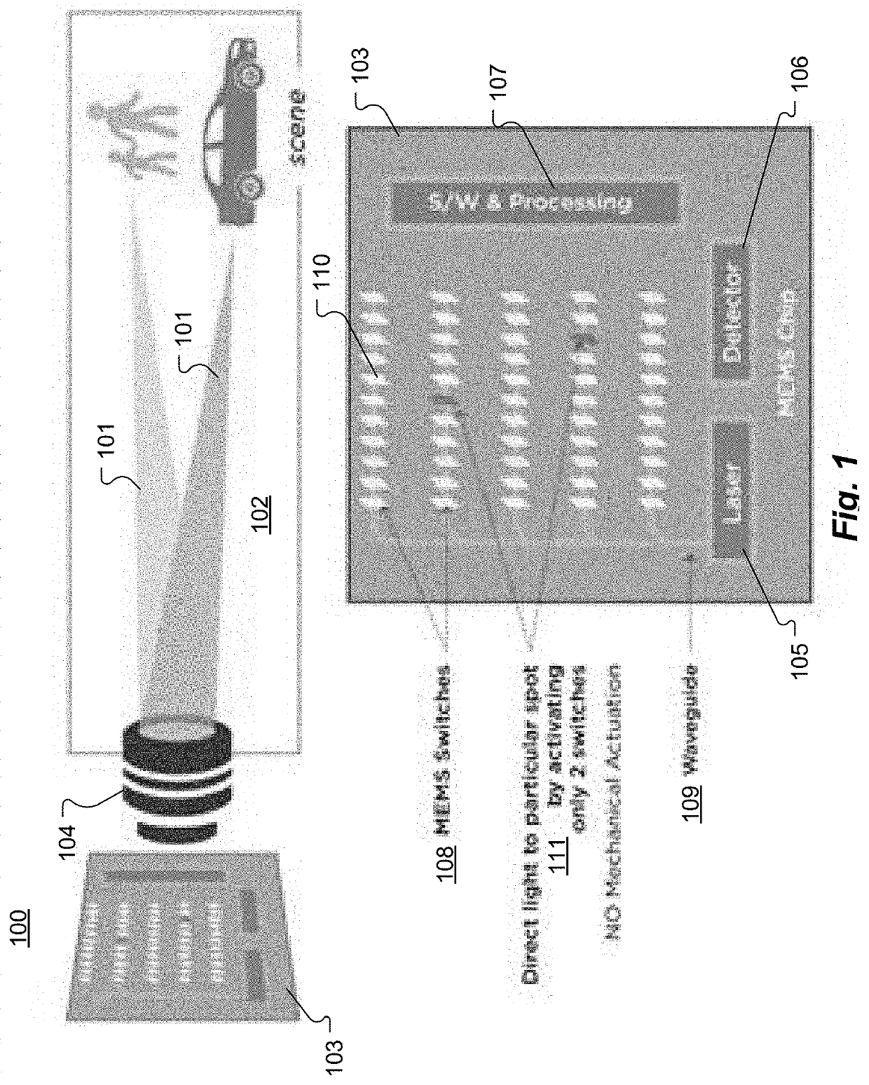
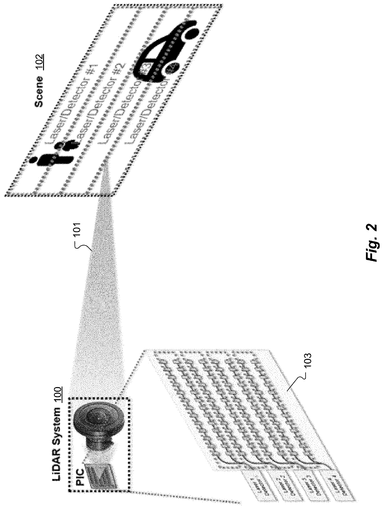
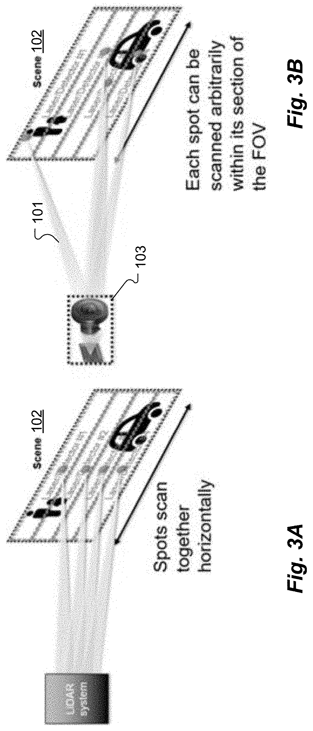
[0023]FIG. 1 shows an overview figure of a LiDAR system 100 according to one embodiment of the present invention that can be configured to emit one or more laser light beams 101 to scan a scene 102 (field of view). The optical circuit includes a photonic integrated circuit (PIC) 103, a lens 104, one or more laser(s) 105, one or more detector(s) 106 and control electronics 107. Light from the laser 105 is coupled into the photonic integrated circuit (PIC) 103 where a series of two or more MEMS switches 108 defines where on the PIC 103 the laser light is emitted. The first MEMS switch 108 may include a MEMS switchable overpass waveguide 109 that couples light from a bus waveguide to a row of optical grating switches 110. An al...


PUM


Abstract

A LiDAR system includes an array of optical emitters, an objective lens optically coupling each optical emitter to a respective unique portion of a field of view, an optical switching network coupled between a laser and the array of optical emitters and a controller coupled to the optical switching network and configured to cause the optical switching network to route light from the laser to a sequence of the optical emitters according to a dynamically varying temporal pattern and to vary the temporal pattern in a way that reduces risk of eye injury from the laser light.

Description

[0001]This application claims priority from U.S. Provisional Patent Application 62 / 751,497, filed Oct. 26, 2018, and from U.S. Provisional Patent Application 62 / 751,500, also filed Oct. 26, 2018, both of which are incorporated herein by reference in their entireties.TECHNICAL FIELD[0002]The present invention relates to LiDAR (light detection and ranging) systems and, more particularly, to LiDAR systems that dynamically varying their temporal scanning patterns to reduce risk of eye injury.BACKGROUND ART[0003]Using multiple beams to scan a scene is a commonly used approach for improving frame rates in LiDAR systems. However, multiple beams increase the risk of laser exposure in the scene. LiDAR systems with the ability to selectively scan regions within a field of view present opportunities to reduce the risks of laser exposure in the scene.SUMMARY[0004]Embodiments of the present invention are directed to a LiDAR system with a field of view that use selective scanning to address the i...

Claims


Application Information

Patent Timeline
IPC IPC(8): H01S3/13G01S13/86G01S17/10G01S17/89
CPCG01S17/89H01S3/1305G01S17/26G01S13/867G01S13/865G02B6/3534G01S17/08G02B6/3548G02B6/3584G02B6/3598G01S7/499G01S17/93
Inventor MOEBIUS, MICHAEL G.SPECTOR, STEVEN J.BYRNES, STEVEN J.BESSETTE, CHRISTOPHERLENNOX, SCOTT EVANSINCLAIR, MATTHEW A.ROGOMENTICH, FRANCIS J.
Owner CHARLES STARK DRAPER LABORATORY
Why Eureka
Try Eureka