Thermal head, thermal printer and manufacturing method for the thermal head

a manufacturing method and thermal head technology, applied in printing, electrical equipment, wave amplification devices, etc., can solve the problems of large power loss, insufficient utilization of heat insulating performance provided by the cavity portion, etc., to reduce heat diffusion, increase printing efficiency, and reduce power loss

Inactive Publication Date: 2013-07-02
SEIKO INSTR INC
View PDF11 Cites 5 Cited by
  • Summary
  • Abstract
  • Description
  • Claims
  • Application Information

AI Technical Summary

Benefits of technology

[0008]The present invention has been made in view of the above-mentioned circumstances, and it is therefore an object of the present invention to provide a thermal head which is capable of suppressing diffusion of heat from a heating resistor in a planar direction of an upper substrate via electrodes so that the printing efficiency may be increased, and to provide a printer including the thermal head. Further, it is another object of the present invention to provide a method of manufacturing the thermal head with ease.

Problems solved by technology

As the ratio of the electrical resistance of the electrode to the electrical resistance of the heating resistor becomes larger, a larger power loss occurs by voltage drop of the electrical resistance from the external input terminals to the heating resistor.
Therefore, the conventional thermal head has a problem that the heat insulating performance provided by the cavity portion cannot be fully utilized because the heat dissipates from the heating resistor in the planar direction of the upper substrate via the electrodes.

Method used


Image

  • Thermal head, thermal printer and manufacturing method for the thermal head
  • Thermal head, thermal printer and manufacturing method for the thermal head
  • Thermal head, thermal printer and manufacturing method for the thermal head

Examples


first embodiment

[0044]Now, a thermal head, a printer, and a manufacturing method for a thermal head according to a first embodiment of the present invention are described below with reference to the accompanying drawings.

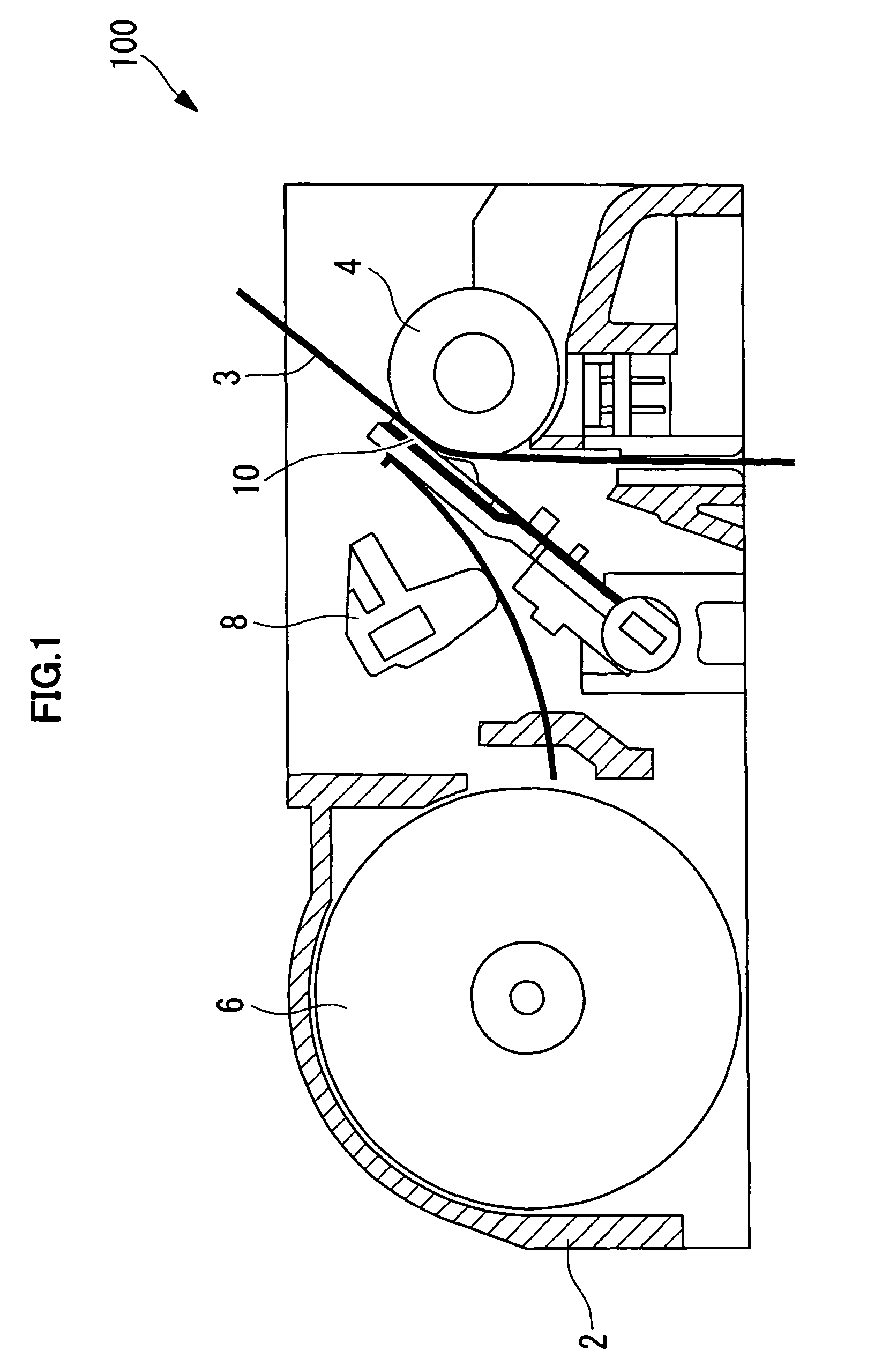
[0045]A thermal printer (printer) 100 according to this embodiment is shown in FIG. 1 and includes a main body frame 2, a platen roller 4 disposed horizontally, a thermal head 10 disposed so as to be opposed to an outer peripheral surface of the platen roller 4, a paper feeding mechanism 6 for feeding an object to be printed, such as thermal paper (thermal recording medium) 3, between the platen roller 4 and the thermal head 10, and a pressure mechanism 8 for pressing the thermal head 10 against the thermal paper 3 with a predetermined pressing force.

[0046]Against the platen roller 4, the thermal paper 3 and the thermal head 10 are pressed by the operation of the pressure mechanism 8. Accordingly, a load of the platen roller 4 is applied to the thermal head 10 via the thermal paper...

second embodiment

[0098]Next, a thermal head, a printer, and a manufacturing method for a thermal head according to a second embodiment of the present invention are described.

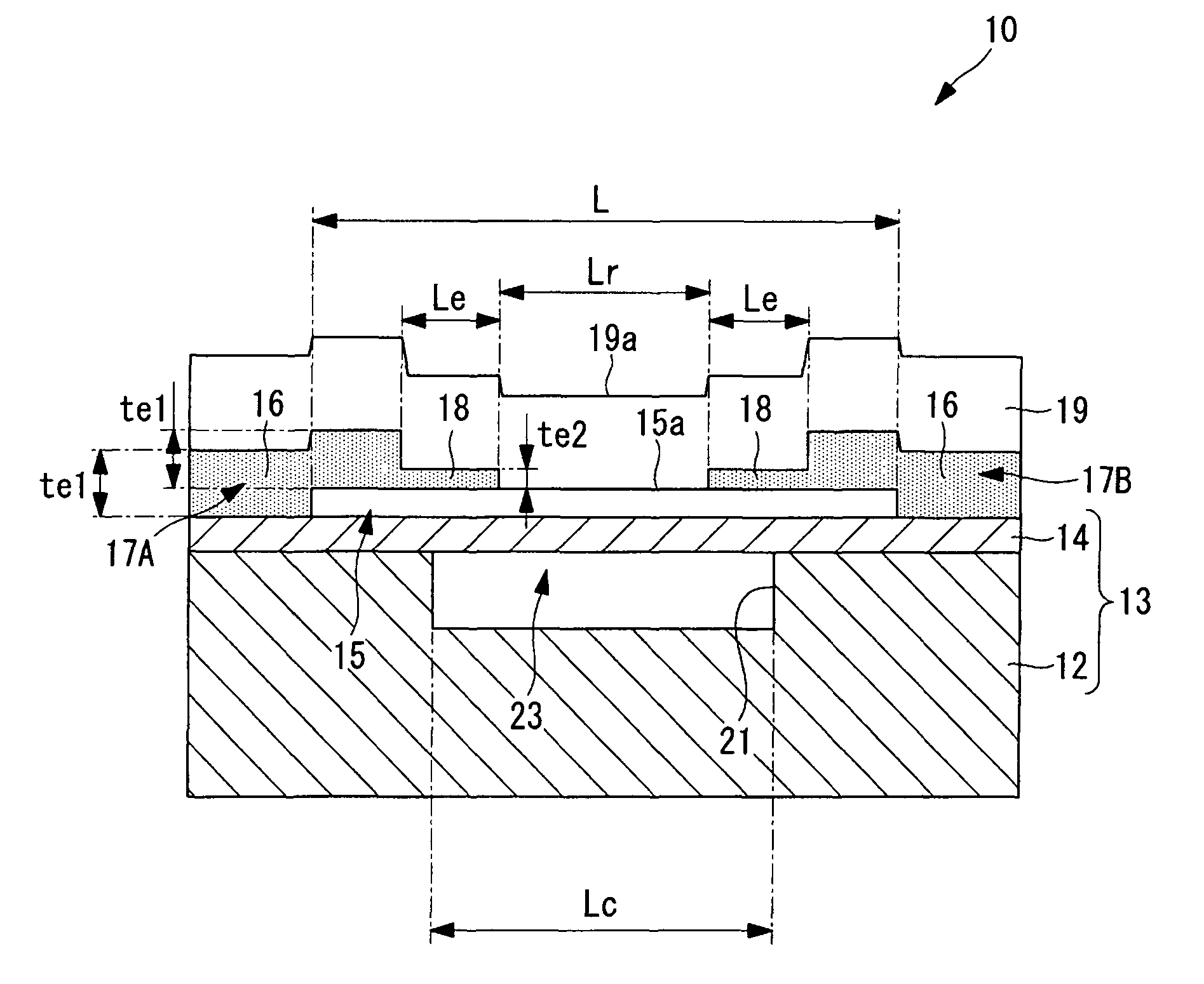
[0099]As illustrated in FIG. 11, a thermal head 110 according to this embodiment is different from the thermal head 10 according to the first embodiment in that electrodes 117A and 117B each include a low thermal conductivity portion 118, which is provided in a region opposed to the cavity portion 23 and made of a material having thermal conductivity lower than other regions and having an electrical resistance lower than that of the heating resistor 15. Hereinafter, parts common to the thermal head 10, the thermal printer 100, and the manufacturing method for a thermal head according to the first embodiment are denoted by the same reference symbols and the descriptions thereof are omitted.

[0100]The electrodes 117A and 117B have a substantially uniform thickness as a whole. In each of the electrodes 117A and 117B, a portion dispo...


PUM

PropertyMeasurementUnit
thicknessaaaaaaaaaa
thicknessaaaaaaaaaa
thickness te2aaaaaaaaaa

Abstract

A thermal head comprises a first substrate having a concave portion, a second substrate mounted on the first substrate and covering the concave portion to form with the first substrate a cavity portion, a heating resistor provided on a surface of the second substrate, and a pair of electrodes connected to the heating resistor for supplying power to the heating resistor. At least one of the pair of electrodes has a low thermal conductivity portion in a region opposed to the cavity portion. The low thermal conductivity portion is made of a material having a thermal conductivity lower than a thermal conductivity in other regions of the pair of electrodes and having an electrical resistance lower than an electrical resistance of the heating resistor.

Description

BACKGROUND OF THE INVENTION[0001]1. Field of the Invention[0002]The present invention relates to a thermal head, a thermal printer, and a manufacturing method for the thermal head.[0003]2. Description of the Related Art[0004]There has been conventionally known a thermal head for use in thermal printers (see, for example, Japanese Patent Application Laid-open No. 2009-119850). In the thermal head described in Japanese Patent Application Laid-open No. 2009-119850, a plurality of heating resistors are formed on a stacked substrate of a support substrate and an upper substrate, and power is supplied to pairs of electrodes connected to the heating resistors, thereby allowing the heating resistors to generate heat to perform printing on a thermal recording medium or the like.[0005]In the thermal head, a cavity portion is formed at a position opposed to each of the heating resistors in a bonding portion between the support substrate and the upper substrate. The cavity portion functions as ...

Claims


Application Information

Patent Timeline
Patent Type & Authority Patents(United States)
IPC IPC(8): B41J2/335
CPCB41J2/3351B41J2/33585B41J2/3354Y10T29/49002
Inventor MOROOKA, TOSHIMITSUKOROISHI, KEITAROSHOJI, NORIYOSHISANBONGI, NORIMITSU
Owner SEIKO INSTR INC
Why Eureka
Try Eureka