Rotatable container interior cleaning mechanism

a rotating container and cleaning mechanism technology, applied in the direction of cleaning equipment, vehicle cleaning, lighting and heating apparatus, etc., can solve the problems of difficult conformity to the many shapes of containers, large size, and laborious designs of previous designs, so as to improve maneuverability, improve control, and quickly dislodge the contents of most containers

Inactive Publication Date: 2013-07-09
SMETANA MATTHEW J
View PDF26 Cites 2 Cited by
  • Summary
  • Abstract
  • Description
  • Claims
  • Application Information

AI Technical Summary

Benefits of technology

[0011]A continuous double torsion spring is also slid over the projection of the pins of the Shield With Double threaded standoff, which extends out past the drive arm holes thru the spirals of the spring. Said projection is then covered by the spacers of the Shield w / double standoff spacer which become contiguous with the spring face of the drive arm. The spacer is long enough to allow the spring to move freely when the lower arms rotate.
[0014]Penetrating thru the hole in the bottom end of the lower arms is another pin which links one end of a swiveling attachment receiver to said lower arms. The pin allows said swiveling attachment receiver to swing away from the lower arms.
[0016]The swiveling attachment receiver has two sweeping edges designed to dislodge any food or material that is stuck to a containers interior when slid across said container's surface. The double edge allows said swiveling attachment receiver to be slid in two opposing directions while still accomplishing the same results. The face of the surface of the swiveling attachment receiver closest to the container is curved away from the container to maximize the contact of the sweeping edges of said swiveling attachment receiver.
[0020]A padded grip wraps around the pivot arm in such a way to allow continuous rotation of the grip around the pivot arm. At both ends of the grip on the pivot arm there are bands where it widens to prevent the grip from sliding in either direction while still allowing it to rotate.
[0021]Such that by Rotating these spring loaded arms more than 90 degrees away from the drive arm creates pressure from the spring to swing the arms back against the drive arm. This pressure when placed inside of a container keeps the spatula-like heads at the ends of the spring loaded arms in continuous contact with the inside walls of the container, to better clean the undulating surfaces of various shaped containers. The gearing of the two lower arms to each other keeps them symmetrical to the drive arm, which keeps the assembly centered to the container, which it is cleaning. This centering helps the crank arm to operate in a smooth rotation with only 1 hand on the mechanism. The padded grip is allowed to rotate around the pivot arm to allow the cranking hand to stay engaged with the mechanism while cranking for better control. This continuous rotation allows the user to quickly dislodge most of the containers contents far quicker and with better maneuverability than the prior art. The fold-down pivot arm, and the range of rotation of the lower arms into the closed position allow the mechanism to take up a minimal amount of space when being stored.

Problems solved by technology

Previous designs were very laborious requiring the spatula to be repeatedly maneuvered within the container while manually rotating the container attempting to bring it's contents to the top and out.
They also had difficulty conforming to the many shapes of containers and would require multiple sizes for multiple shaped containers.
Additionally they are typically too large to be effective to fit into a container with a wide base and narrow neck.
They also had difficulty removing the contents that might collect at the angled part just below the neck of the container.
These devices would only work for round semi smooth containers of consistent shape.
These devices are expensive, are required to be plugged in, are very cumbersome, and primarily immobile.
This prior art is limited in it's ability to make lineal contact with the walls of a container.
It has far more surface area to it, making it's cleanup more difficult.
It is too wide to fit within a narrow necked container, and it is also not capable of folding down to a compact size for storage.

Method used


Image

  • Rotatable container interior cleaning mechanism
  • Rotatable container interior cleaning mechanism
  • Rotatable container interior cleaning mechanism

Examples


Embodiment Construction

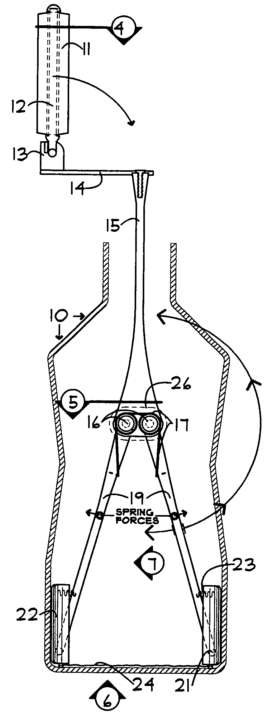
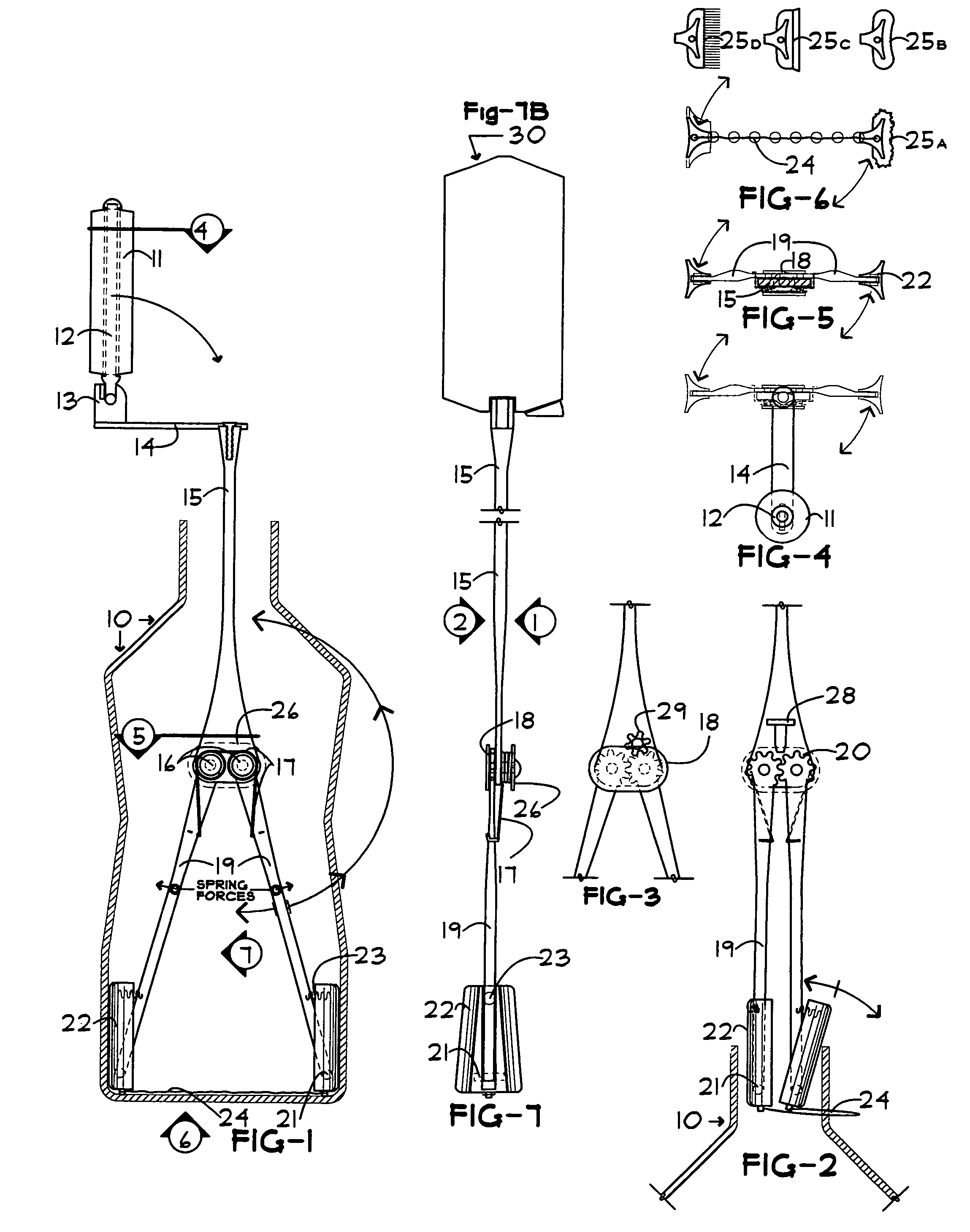
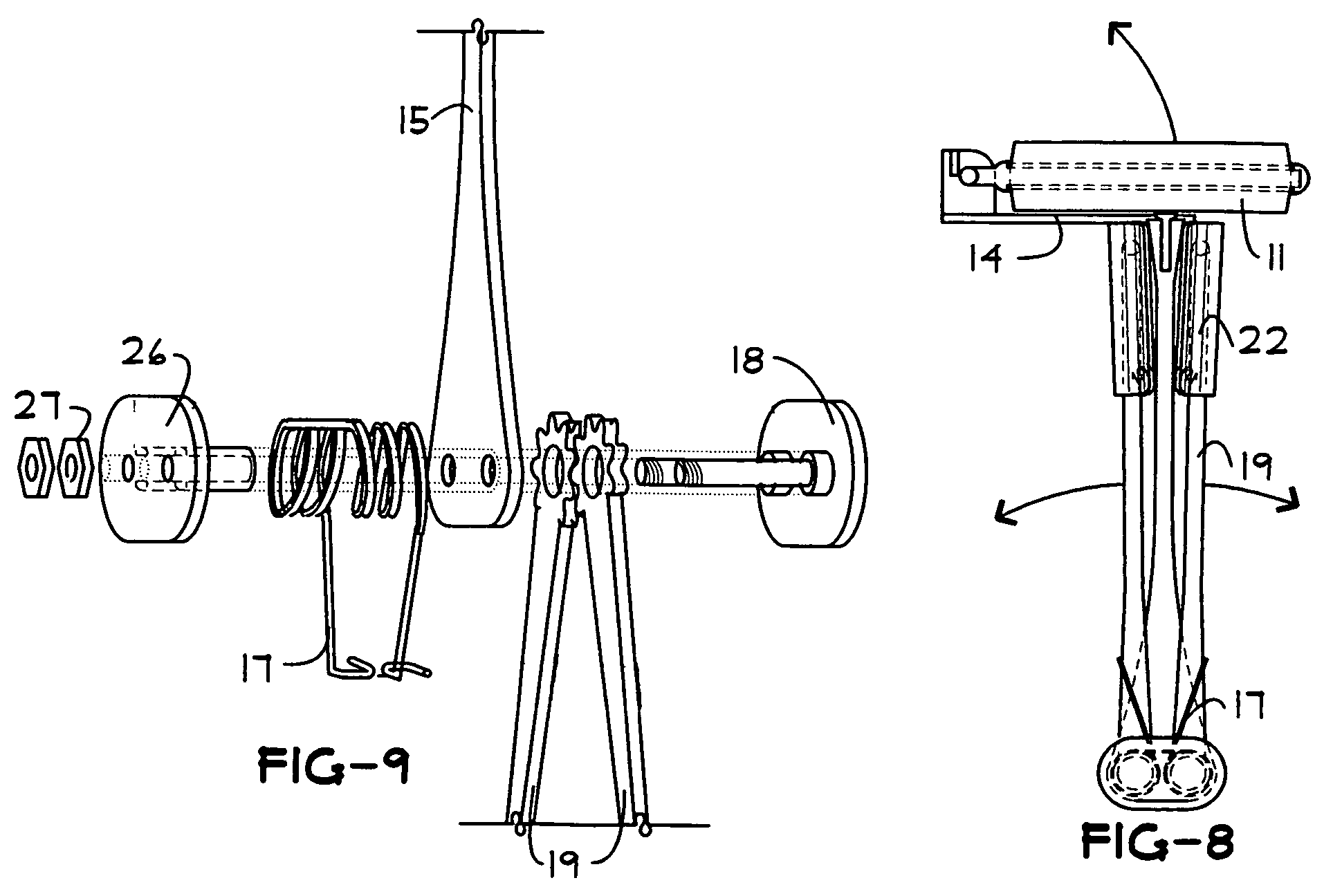
[0032]10. Container To Be Cleaned (oriented With Opening Angled Down When Using Mechanism).[0033]11. Padded Grip, which freely Rotates Around (12) the Grip Pivot Arm.[0034]12. Grip-Pivot Arm which pivots in relation to (14) the crank arm, with stops at either end of (11) the padded grip to prevent the grip from sliding out of position.[0035]13. Grip Arm Receiver, with a stop at 90 degrees, permanently attached to (14) the crank arm, and linking (12) the grip-pivot arm by a pin allowing 90-degree rotation.[0036]14. Crank Arm mechanically or permanently Attached at it's opposite end To The top of (15) the Drive Arm.[0037]15. Drive Arm linking the (14) crank arm to the (19) lower arms.[0038]16. Double Hole In Drive Arm to receive pins for lower arms.[0039]17. Double Torsion Spring Around Sleeves of (26) Shield w / double standoff spacer, with the ends hooked around (19) the rotating lower arms. Each Half of the double spring applies rotational pressure opposite The Other onto the lower ...


PUM


Abstract

A hand-held, collapsible, self-adjusting mechanism, which is an improvement to the Spatula, for removing the remaining contents inside a plurality of containers. The device consists of three attached arms, two lower arms geared around their pivot ends to each other to keep their rotation symmetrical in relation to a drive arm, and pressurized with a double torsion spring to rotate towards said drive arm to apply pressure to a swiveling attachment receiver at the opposite end which makes contact with the inside walls of a container. The drive arm has a foldable crank arm assembly which allows you to quickly rotate and slide the mechanism in and out within a container with one hand while the other hand supports said container thus removing the contents from the walls of the container without difficulty or a mess.References CitedU.S. Patent Documents2,065,866 A * December 1936 Clift15:2457,182,377 B2294 / 75,674,042 B65B 69 / 00414 / 4206,424,812 B1399 / 2623,934,300 15 / 2445,626,683134 / 85,732,434 15 / 93.15,491,868 15 / 236.09D262,428 D7 / 1504,106,193 30 / 1722,188,1142,065,8861,228,437, 1,184,606, 1,180,23015 / 104.18US 2005 / 0264017 A1Foreign Patent DocumentsSU001774860* November 1992 294:7EP0854099 (A1)B65D88 / 68

Description

BACKGROUND OF THE INVENTION[0001]1. Field of the Invention[0002]The present invention is related to scrapers and spatulas which are used to obtain the contents which have clung to the inner walls and floor or ceiling of a plurality of container including pipes.[0003]2. Description of Related Art[0004]In the prior art most spatulas are made of various shaped scraper ends with various shaped handles. The spatula end is semi flexible, yet rigid enough to detach the contents of the container without permanently deforming the spatula. Previous designs were very laborious requiring the spatula to be repeatedly maneuvered within the container while manually rotating the container attempting to bring it's contents to the top and out. They also had difficulty conforming to the many shapes of containers and would require multiple sizes for multiple shaped containers. Additionally they are typically too large to be effective to fit into a container with a wide base and narrow neck. They also h...

Claims


Application Information

Patent Timeline
Patent Type & Authority Patents(United States)
IPC IPC(8): A46B13/02
CPCB08B9/087
Inventor SMETANA, MATTHEW J.
Owner SMETANA MATTHEW J
Why Eureka
Try Eureka