
Device for processing feedstock

a technology for feedstock and rotor tools, which is applied in the direction of wet separation, gas current separation, food science, etc., can solve the problems of large amount of work, large impact on the quality of processed end products, and substantial mounting costs, and achieve the effect of rapid change of rotor tools

Inactive Publication Date: 2013-07-09
PALLMANN MASCHFAB GMBH & CO KG
View PDF17 Cites 0 Cited by
  • Summary
  • Abstract
  • Description
  • Claims
  • Application Information

AI Technical Summary

Benefits of technology

This design reduces tool replacement downtime, enhances machine performance by allowing more circumferential planes and active edges, and provides latitude in geometric configuration, resulting in improved processing efficiency and flexibility.

Problems solved by technology

Depending on the type of feedstock and the type of processing, generic devices are equipped with suitable rotor tools, which because of the intense contact with the feedstock are subject to more or less extensive wear, which starting at a certain degree has a negative impact on the quality of the processed end product.
A disadvantage of this device arises from the type of attachment of grinding plates to the rotor discs with the use of screws.
The arrangement of several grinding stages axially one behind the other and the plurality of grinding plates per grinding stage result in substantial mounting costs during the wear-related change of the grinding plates.
Moreover, a considerable amount of work is associated, furthermore, with the successive changes of the individual rotor tools.
In addition, it is a disadvantage in all of the aforementioned devices that the geometric configuration of the crushing zone is possible only within narrow limits.

Method used


Image

  • Device for processing feedstock
  • Device for processing feedstock
  • Device for processing feedstock

Examples


Embodiment Construction

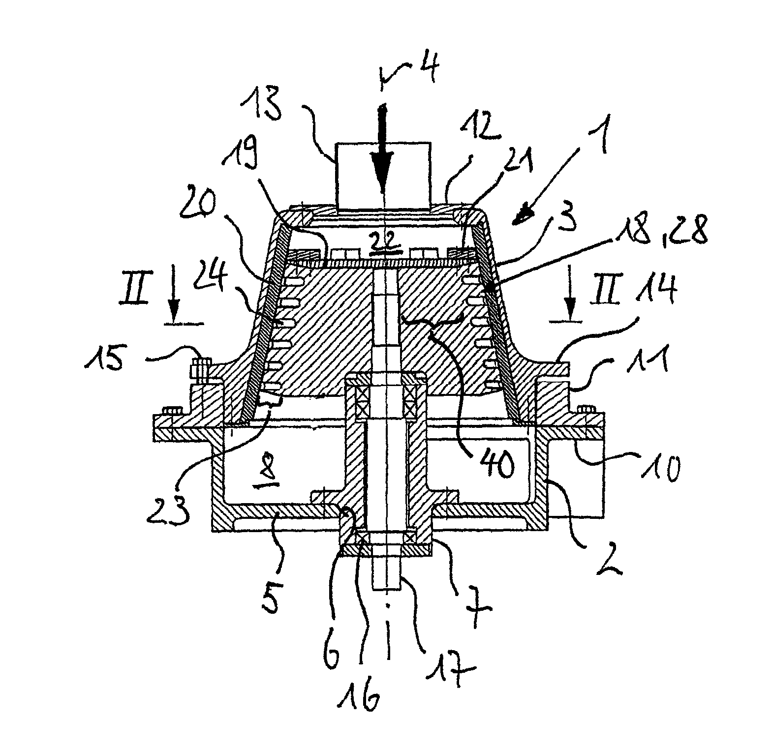
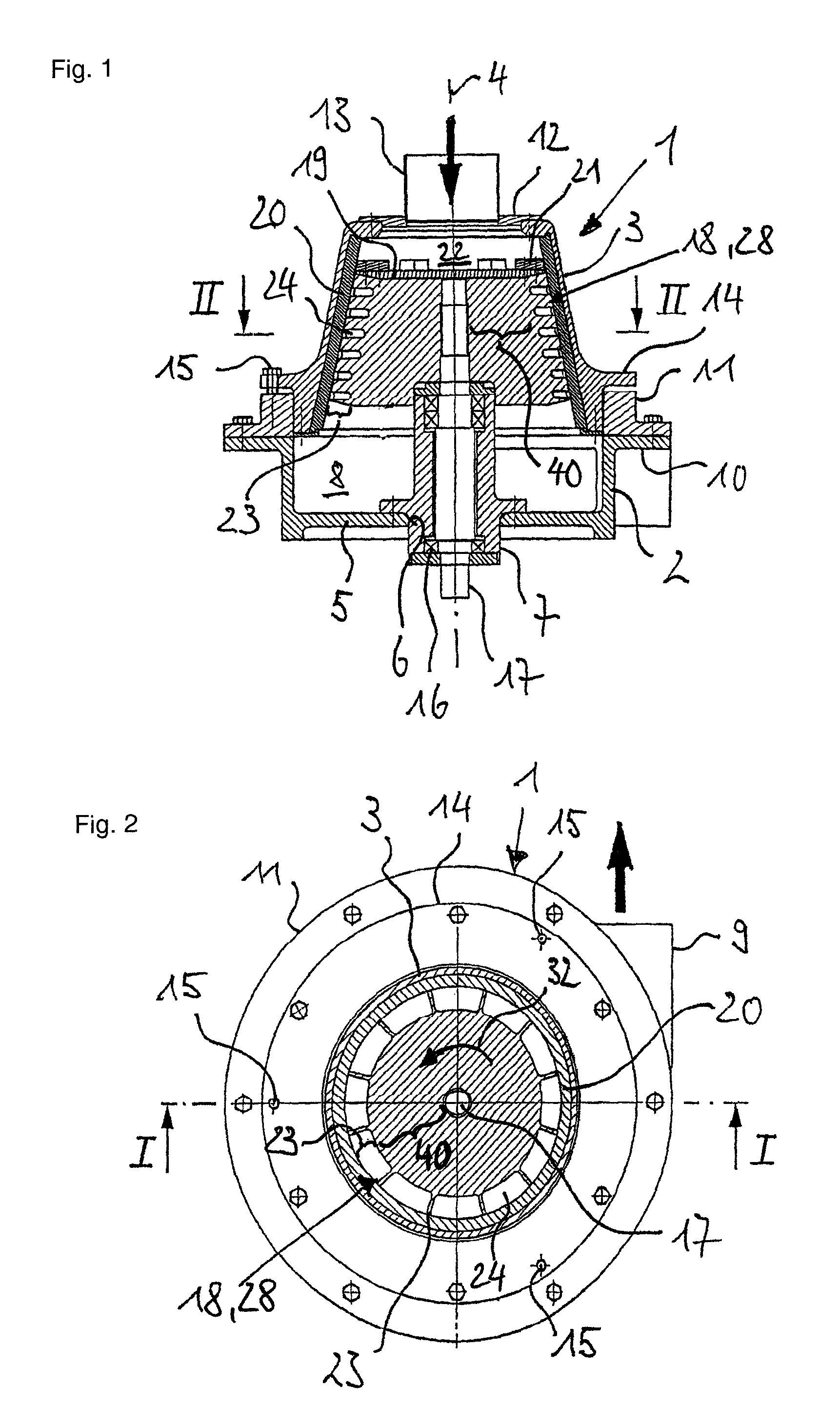
[0028]The general structure of a device of the invention emerges from FIGS. 1 and 2. Evident there is a housing 1, which is made up of a cylindrical bottom part 2 and a bell-shaped top part 3. The longitudinal axis of housing 1 is provided with the reference character 4. The bottom part 2 is closed downward by a bottom 5 in which a circular opening 6 is disposed centric to axis 4. Opening 6 is used for accommodating an essentially cylindrical shaft bearing 7, which is screwed on coaxially to axis 4 by means of a flange connection on bottom 5. The upper end of shaft bearing 7 extends into the area of the top part 3. An annular channel 8, which opens out of housing 1 via a material outlet 9, tangential to axis 4, results in this way within the bottom part 2. The upper closure of the bottom part 2 is formed by a circumferential annular flange 10, to which a bearing ring 11, angular in cross section, is attached.

[0029]As already mentioned, the outer form of the top part 2 is bell-shaped...


PUM


Abstract

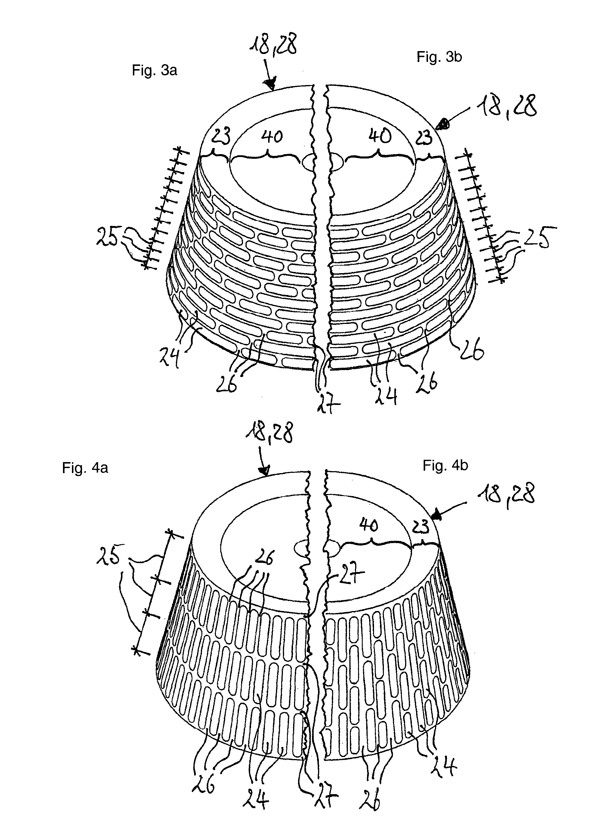
A device for mixing, grinding, drying, deagglomeration, crushing, or coating of feedstock with a rotor is provided, rotating around an axis within a housing, and a stator, fixed relative to the housing, encompassing the rotor with maintenance of a radial working gap. The rotor has rotor tools, which are distributed over its outer surface and whose active edges for crushing the feedstock work together with the stator tools on the inner circumference of the stator. In this regard, the feedstock is supplied in the carrier gas stream to the working gap. For effective processing of the feedstock, it is proposed according to the invention that in the outer surface of the rotor a plurality of indentations is introduced, whereby areas between two adjacent indentations form webs, which form the active edges of the rotor tools.

Description

[0001]This nonprovisional application claims priority under 35 U.S.C. §119(a) to German Patent Application No. DE 10 2009 020 714.7, which was filed in Germany on May 11, 2010, and which is herein incorporated by reference.BACKGROUND OF THE INVENTION[0002]1. Field of the Invention[0003]The invention relates to a device for processing feedstock.[0004]2. Description of the Background Art[0005]Conventional devices for processing feedstock belong to the field of mechanical process engineering. This concerns changing a source material in its form, size, and / or composition. For example, during crushing, grinding, or deagglomeration, a source material is taken from an original size to a comparatively smaller form. During mixing, different components in the feedstock are prepared so that a uniform particle distribution in the feedstock is achieved at the end. During coating or drying, heat is introduced selectively into the feedstock with the processing of the feedstock, to enclose individu...

Claims


Application Information

Patent Timeline
Patent Type & Authority Patents(United States)
IPC IPC(8): B02C18/18
CPCB02C2/10B02C13/14B02C2013/145
Inventor PALLMANN, HARTMUT
Owner PALLMANN MASCHFAB GMBH & CO KG
Learn More