Vehicle body rear structure

a rear structure and vehicle technology, applied in the direction of roofs, vehicle arrangements, transportation and packaging, etc., can solve the problems of deformation or damage of the fuel tank, insufficient absorption of shock energy,

Inactive Publication Date: 2013-07-09
SUZUKI MOTOR CORP
View PDF20 Cites 9 Cited by
  • Summary
  • Abstract
  • Description
  • Claims
  • Application Information

AI Technical Summary

Benefits of technology

[0006]The present invention has been made in view of the above circumstances, and accordingly, an object thereof is to provide a vehicle body rear structure that can restrain deformation of a rectangular region, which is surrounded by front and rear rear-floor cross members and right and left rear-floor cross member braces, caused a shock load applied to a vehicle body rear part from the rear, can prevent parts disposed in this region from being damaged, and can absorb shock energy efficiently.
[0008]As described above, the vehicle body rear structure in accordance with the present invention is configured so that the second rear-floor cross member positioned on the rear of the first rear-floor cross member is formed by the three-member connected body consisting of the right and left extension parts and the body part arranged therebetween, and the paired right and left rear-floor cross member braces are connected to the body part of the second rear-floor cross member. Therefore, deformation caused by a shock load applied to the vehicle body rear part from the rear is guided to the right and left extension parts that are liable to be deformed as compared with a rectangular region (rectangular frame part) surrounded by the first and second rear-floor cross members and the right and left rear-floor cross member braces, and shock energy can be absorbed efficiently while the floor rigidity of the vehicle body rear part contributing to the running stability is maintained. Also, deformation of the rectangular region is restrained, and the parts disposed in this region can be prevented from being damaged.
[0010]In this aspect, the deformation of the right and left extension parts is guided by the improved rigidity of the second rear-floor cross member body part, and the deformation of the rectangular region is further restrained. Therefore, the parts disposed in this region can be prevented from being damaged more surely, and the load from a spare tire housing to the second rear-floor cross member can surely be transmitted to the first rear-floor cross member. Also, the width in the vehicle longitudinal direction of the body part can be decreased, the installation space of the spare tire housing can be secured easily, and the degree of freedom for vehicle body design of this part can be increased while rigidity necessary for the body part is maintained by the second reinforcement.
[0012]In this aspect, by the deformation, which is caused by the shock load applied to the vehicle body rear part from the rear, of the right and left extension parts of the first rear-floor cross member in addition to the right and left extension parts of the second rear-floor cross member, shock energy can be absorbed efficiently. Also, by the deformation of these four extension parts, the deformation of the rectangular region itself surrounded by the first and second rear-floor cross member body parts and the right and left rear-floor cross member braces is restrained, and the parts disposed in this region can be prevented from being damaged. Also, since the rectangular region (rectangular frame part) is deformed forward while its shape is maintained, even if the rectangular region comes into contact with a fuel tank or other parts arranged in the front, the whole of the first rear-floor cross member body part extending in the vehicle width direction comes into contact with the rear surface of the fuel tank, so that local contact with the fuel tank and deformation caused by this contact can be prevented.
[0014]In this aspect, if a shock load is applied to the vehicle body rear part from the rear, the load applied to the rectangular region from the rear is transmitted to the rear-floor side members on both sides in the vehicle width direction via the right and left first reinforcements. Since the load is distributed to the whole of a monocoque body structure, the deformation of a cabin can be kept at a minimum. Also, main deformation is guided to portions around the parts in which the extension part of the second rear-floor cross member and the extension part of the first rear-floor cross member are attached to the rear-floor side member. Therefore, even if the shock energy is excessive, the deformation of the rectangular region is restrained, and the load applied to the parts disposed in this region and the fuel tank or the like provided in front of this region can be reduced more surely.
[0016]In this aspect, the rectangular frame part formed by the body parts of the first and second rear-floor cross members and the right and left rear-floor cross member braces is detachable, so that the assembly and maintenance of the parts disposed in the frame part can be accomplished easily.

Problems solved by technology

However, if the rigidity of the entirety of the rear-floor is too high, the amount of deformation produced when a shock load is applied from the rear is small, so that there is a possibility that the shock energy will not be absorbed sufficiently.
In the case in which the absorption of energy in this region is insufficient, the rear-floor cross members are moved frontward by the remaining shock load and come into contact with a fuel tank, and this may deform or damage the fuel tank.

Method used


Image

  • Vehicle body rear structure
  • Vehicle body rear structure
  • Vehicle body rear structure

Examples


Embodiment Construction

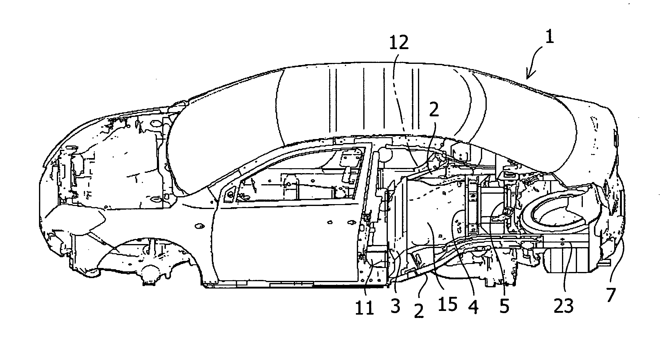
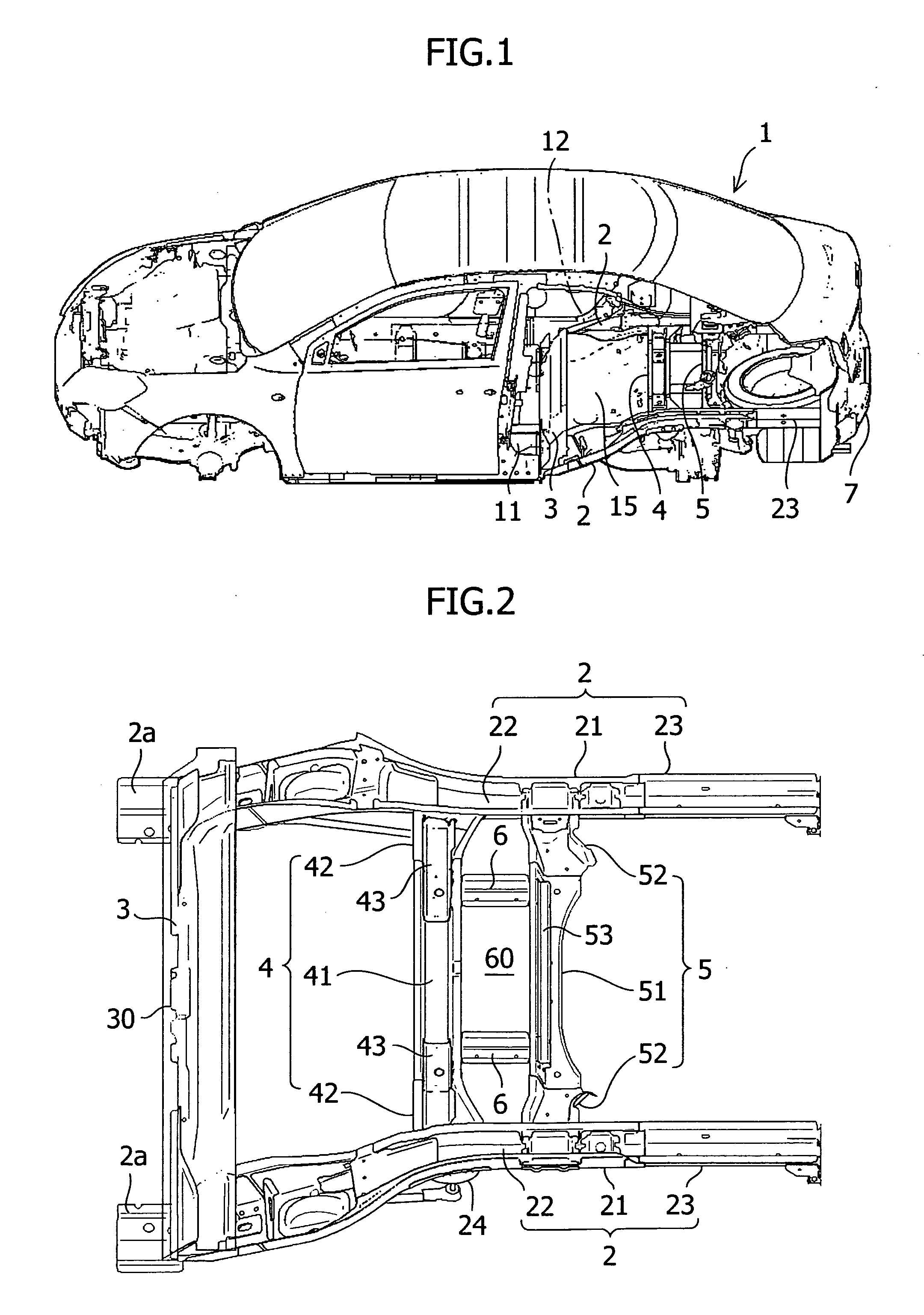
[0022]An embodiment of the present invention will now be described in detail with reference to the accompanying drawings. In FIG. 1, a rear-floor 12 on the rear of a rear seat position of the vehicle 1 is provided at a position higher than a front floor 11, and rear-floor side members 2, 2 are disposed along both side portions of the rear-floor 12.

[0023]Each of the rear-floor side members 2, 2 rises slantwise toward the rear from the front floor 11, reaching the height of the rear-floor 12 in a cabin rear part while curving toward the center in the vehicle width direction to avoid a wheel house 14, 14 for a rear wheel as shown in FIG. 5, and extending linearly toward the vehicle rear end. Between the right and left rear-floor side members 2, 2, three rear-floor cross members 3, 4 and 5 are provided so as to be separated in the vehicle longitudinal direction.

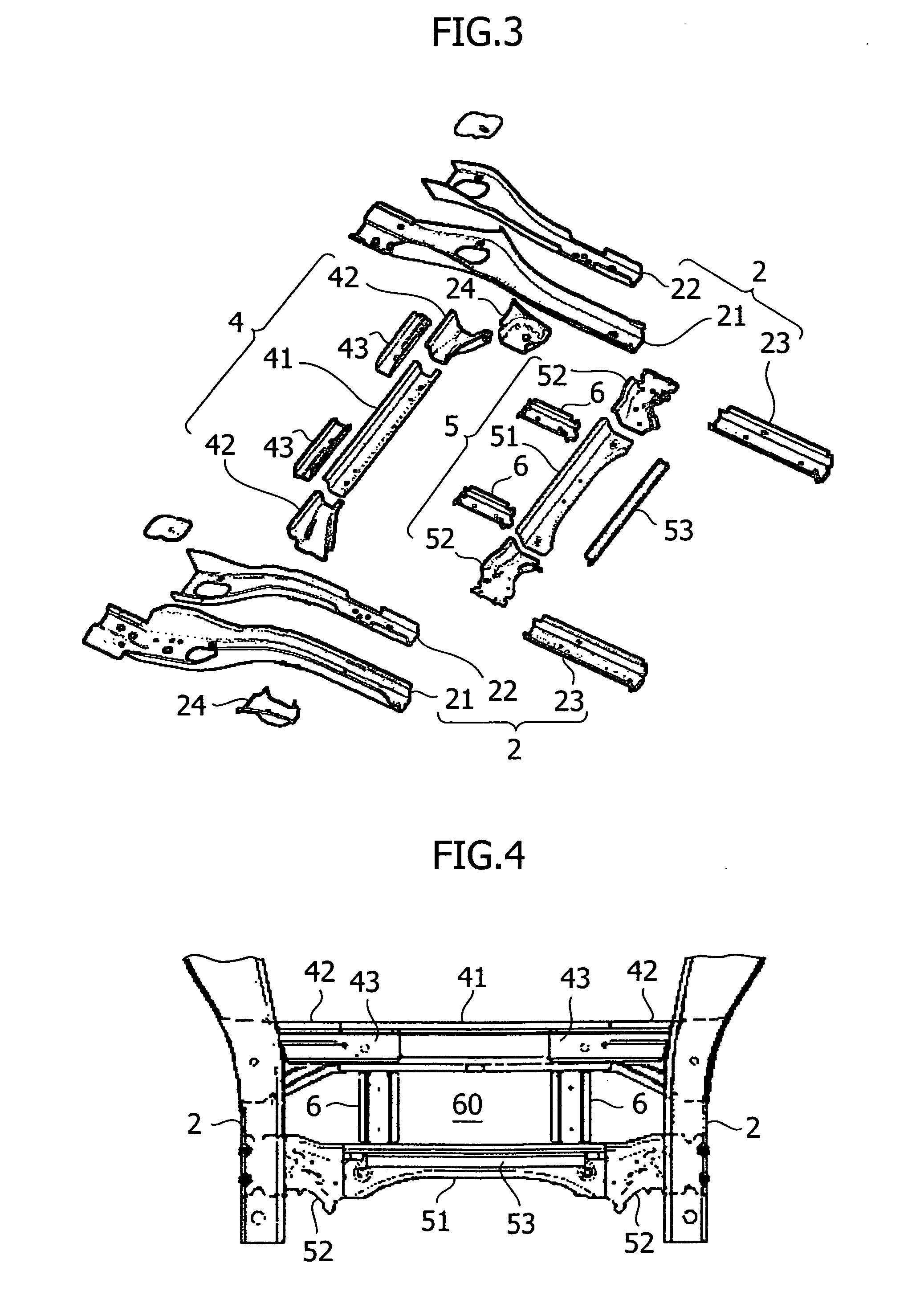
[0024]FIG. 2 is a perspective view of an essential portion of the vehicle body rear structure, showing a frame structure of a v...


PUM


Abstract

A vehicle (1) includes first and second rear-floor cross members (4, 5) provided between right and left rear-floor side members (2, 2) in a vehicle body rear part and a pair of right and left rear-floor cross member braces (6, 6) provided therebetween. The second rear-floor cross member is formed by a three-member connected body consisting of right and left extension parts (52, 52) connected to the right and left rear-floor side members and a body part (51) arranged therebetween. The rear-floor cross member braces are connected to the body part (51) of the second rear-floor cross member. Shock energy of a shock load applied to the vehicle body rear part from the rear can be absorbed efficiently while the deformation of a rectangular region surrounded by the first and second rear-floor cross members and the right and left rear-floor cross member braces is restrained.

Description

CROSS-REFERENCE TO RELATED APPLICATIONS[0001]The present application claims priority from Japanese Patent Application No. JP 2008-243714, filed in the Japanese Patent Office on Sep. 24, 2008, the entire content of which is incorporated herein by reference.BACKGROUND OF THE INVENTION[0002]The present invention relates to a vehicle body rear structure of an automobile.[0003]For a passenger car having a monocoque body structure, in comparison with a front floor that is made low to secure an interior space, in a vehicle body rear part on the rear of a rear seat, a rear-floor is provided at a position higher than the front floor to utilize a space under the rear seat as an installation space for a fuel tank and the like. For the rear-floor, rear-floor side members are provided along both side parts thereof, and rear-floor cross members are provided between the right and left rear-floor side members.[0004]In such a vehicle body rear structure, to improve the rigidity of the rear-floor, in...

Claims


Application Information

Patent Timeline
Patent Type & Authority Patents(United States)
IPC IPC(8): B62D21/00
CPCB62D25/087B62D25/2027
Inventor KOYAMA, HIROYUKIUCHIDA, KOJI
Owner SUZUKI MOTOR CORP
Why Eureka
Try Eureka