
Bone plate system

a technology of bone plate and plate plate, applied in the field of bone plate system, can solve the problems of tearing soft tissues supporting the spine, breaking bones, and deteriorating bones

Active Publication Date: 2013-07-09
XTANT MEDICAL HLDG INC
View PDF82 Cites 29 Cited by
  • Summary
  • Abstract
  • Description
  • Claims
  • Application Information

AI Technical Summary

Benefits of technology

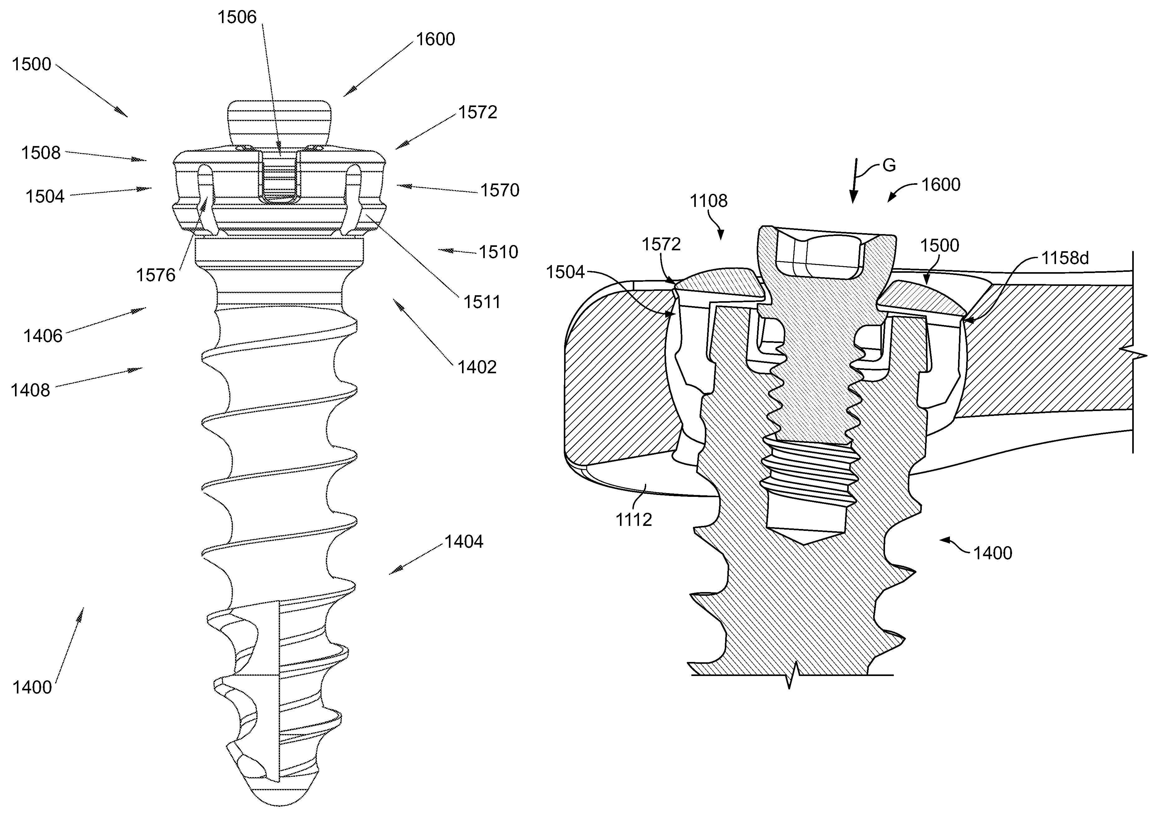
The present invention provides a bone plate system with a centrally positioned through bore and an elongate bone anchor that can be inserted at large angles through the bone plate without getting caught on the plate. The bone anchor has a locking cap with projections that align with the bore and a set screw that is engaged to the anchor head. The spacing between the set screw and the locking cap allows the projections to shift radially inward, allowing the anchor to be inserted at large angles without catching on the plate. This results in a more secure and precise bone plate system for stabilizing bones.

Problems solved by technology

For example, sudden trauma may break bones or tear soft tissues which support the spine.
Alternatively, genetic disorders, tumors, or infections may cause bones to deteriorate.
Further, excessive movement of one vertebral body relative to another may cause compression of the spinal cord or nerves.
Patients who suffer from one or more of these conditions often experience extreme and debilitating pain, and may incur permanent neurologic damage if the conditions are not properly treated.
Engaging the bone anchor with the end plate in some instances is undesirable as the bone anchor may cause a weakened end plate to fracture or otherwise reduce the end plate's load bearing capacity.
Many prior bone plate systems fail to provide the desired functionality and ease of use required by a number of bone fusion procedures.
One such shortcoming is that many bone plate systems fail to resist backing out or loosening of the bone anchors, which are often bone screws.
If the bone screws loosen, the bones are not properly secured and may be allowed to move relative to one another in an uncontrolled manner.
This may compromise the ability to achieve optimal bone fusion and bone alignment, and it may lead to loss of graft material and damage or loss of bone.
Furthermore, when the plate is located in the lumbar or sacral regions of the spinal column with heavy loading and movement of the vertebrae, these issues may be further compounded or exacerbated.
Additionally, in the case of anterior lumbar or anterior sacral plates, a bone screw backing out could cause irritation or a puncture wound to internal organs, or even damage to the circulatory or nervous systems.
When the bone plate is located in the lumbar or sacral region of the spinal column, this approach is undesirable because weakening the bone screw head may cause the head material to yield or otherwise deform when subjected to loading of the vertebra.
Failure or deformation of the bone screw head may also compromise the stability of the bone plate system which, in turn, could cause the bone fusion procedure to fail.
Another problem with these configurations is that the stress on the system may lead to the set screw backing out over time.
In prior bone plates, the movement of the bushing is limited to the confines of the bore in which the bushing is received.
As is apparent, the angle at which the bone screw is inserted through the bore and into a bone is similarly limited by the limited movement of the bushing within the bone plate bore.
Further, the insertion angle of the bone screw may also be limited by contact between the bone screw and the bone plate as the bone screw is driven into the bone plate bore.
One problem with bushings that are placed into bone plate bores is the assembly time this requires.
Another problem with this arrangement is that the surgeon has to align the bone screw with the opening in the bushing before passing the bone screw therethrough.
This complicates the process of fastening the bone plate onto the bones and increases the duration of the surgical procedure.
Not only does the large set screw require time-intensive installation, but it also extends a significant distance above the head of the bone anchor such that a thicker bone plate is required to limit the distance the set screw projects into the body.

Method used


Image

  • Bone plate system
  • Bone plate system
  • Bone plate system

Examples


Embodiment Construction

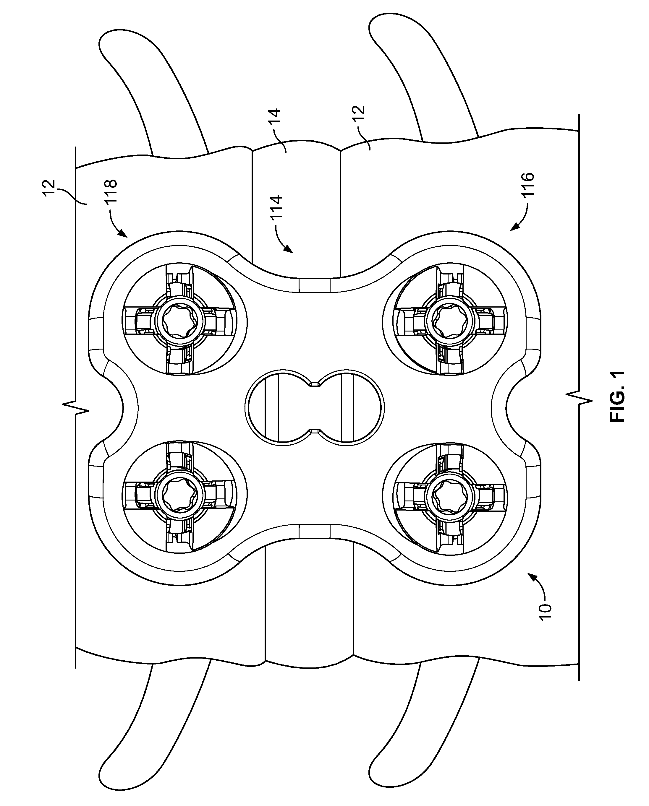
[0079]Referring initially to FIG. 1, a bone plate system 10 is depicted shown connected on the anterior surface of adjacent lumbar vertebrae 12 that are spaced by an intervertebral disc 14. In general, the bone plate system 10 may be used to secure one or more bones in a desired spatial relationship to aid in their healing. The bone plate system 10 may also be used to assist in the healing necessary after trauma or degenerative disorders have affected the intervertebral disc 14. Furthermore, the bone plate system 10 may be used to correct and / or relieve a variety of spinal disorders, including but not limited to degenerative disorders, disorders induced by trauma, and pinched nerves.

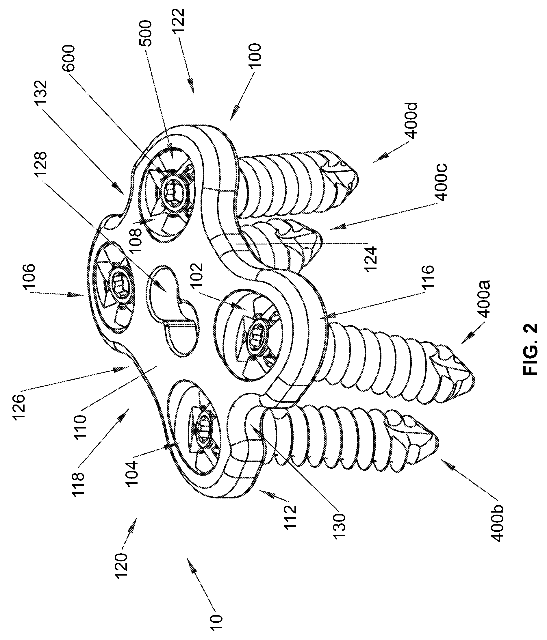
[0080]Turning to FIG. 2, the bone plate system 10 is shown having a bone plate 100 and bone anchor assemblies 400a-400d. The bone plate 100 is generally configured to be placed on one or more bones before bone anchor assemblies 400 are inserted into through bores 102, 104, 106, 108 which extend between u...


PUM


Abstract

A bone plate system is provided that includes bone plates and bone anchor assemblies for being inserted into bone plate bores to secure the bone plates to one or more bones. In one aspect, the bone plate system includes a bone anchor assembly having a locking cap and a locking fastener connected to a head portion of a bone anchor. The bone anchor assembly is driven into a bone plate bore before the locking fastener is shifted to expand the locking cap and fix the bone anchor assembly within the bore. In another aspect, the bone plate system includes a bone anchor assembly having a locking cap that deflects radially inward due to contact with the bone plate at large bone anchor assembly insertion angles. In addition, a bone anchor assembly having a preassembled condition with a locking cap resisting back out of a locking fastener.

Description

CROSS-REFERENCE TO RELATED APPLICATIONS[0001]This application claims the benefit of U.S. Provisional Application Ser. No. 61 / 047,926, filed Apr. 25, 2008, which is hereby incorporated by reference as if fully set forth herein.FIELD OF THE INVENTION[0002]The invention relates to a bone plate system and, more particularly, to a bone plate system that allows for polyaxial bone anchor insertion and rigid fixation of the bone anchor relative to a bone plate.BACKGROUND OF THE INVENTION[0003]There are presently many different types of plate and fixture systems for securing two or more bones or bone fragments in relative position so that the bones may fuse or heal, or so that tissue adjacent the bones may heal without disruption from the movement of the secured bones. As used herein, the term bone may refer to a bone, or a bone fragment or portion, and the term may refer to a portion of a bone that is covered with another material, such as the endplates covering the top and bottom surface o...

Claims


Application Information

Patent Timeline
Patent Type & Authority Patents(United States)
IPC IPC(8): A61B17/80
CPCA61B17/8038A61B17/8047A61B17/7059
Inventor PERROW, SCOTT J.FREDIN, BRAD
Owner XTANT MEDICAL HLDG INC
Learn More