
Imagery optical system

a technology of optical system and optical lens, applied in the field of imagery optical system, can solve the problems of not meeting the requirements of compact electronic devices, the total length of the optical system is not applicable for compact electronic devices, and the gap between the third lens element and the fourth lens element is not favorable to achieving a shorter total length, so as to achieve good aberration correction and modulation transfer function (mtf), the effect of reducing the total length of the optical lens assembly

Active Publication Date: 2013-07-09
LARGAN PRECISION
View PDF21 Cites 23 Cited by
  • Summary
  • Abstract
  • Description
  • Claims
  • Application Information

AI Technical Summary

Benefits of technology

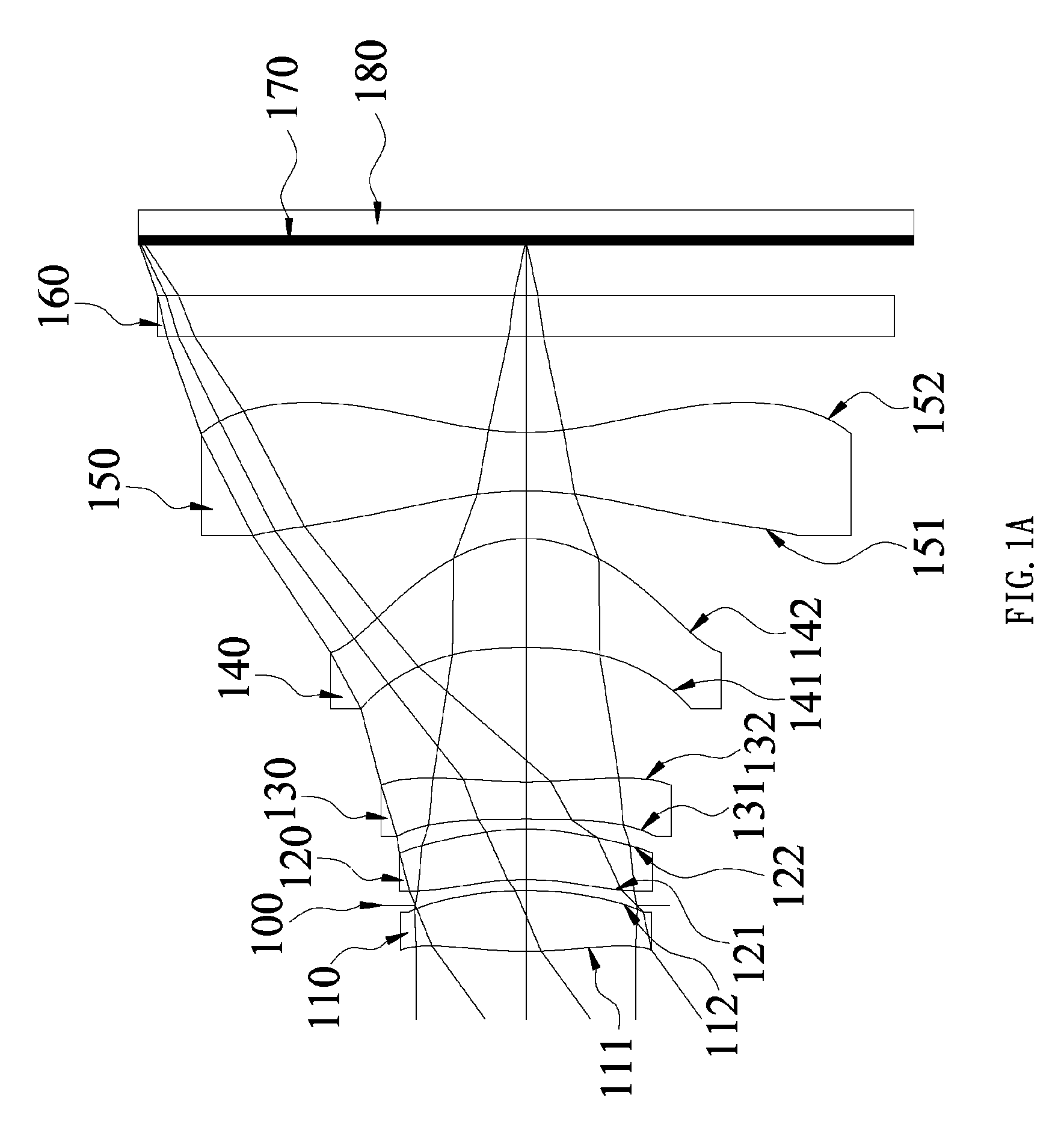
[0028]With appropriate gaps among the first lens element, second lens element, third lens element, fourth lens element and fifth lens element of the present invention, the total length of the optical lens assembly can be shortened and good aberration correction and modulation transfer function (MTF) can be achieved effectively and applied to compact electronic device with a camera function.
[0029]In the imagery optical system of the present invention, the first lens element and the second lens element come with positive refractive power for providing a greater positive refractive power to the first lens element and the second lens element, and the third lens element comes with negative refractive power for correcting any aberration produced by the first lens element and the second lens element and for correcting the color difference of the system effectively. Similarly, the fourth lens element comes with positive refractive power for providing an effective refractive power between the fourth lens element and the fifth lens element, and the fifth lens element is provided for correcting the aberration and color difference of images of the fourth lens element and adjusting the modulation transfer function (MTF) to enhance the overall resolution of the imagery optical system, such that the image aberration and distortion of the imagery optical system can meet the high resolution requirement. For different applications, if it is necessary to increase the refractive power of the fifth lens element and correct the aberration and color difference of the image of the fourth lens element, the fifth lens element with positive refractive power is adopted.
[0030]In the imagery optical system of the present invention, through the combination of the first lens element with positive refractive power, the second lens element with positive refractive power, and the third lens element with negative refractive power, and the compensation of the fourth lens element with positive refractive power and the fifth lens element with positive or negative refractive power, the total length of the imagery optical system can be effectively shortened, such that a greater effective pixel range of the image sensor can be achieved in the same total length. In other words, a shorter imagery optical system can be designed within the same effective pixel range of the image sensor.
[0031]In the imagery optical system of the present invention, the fifth lens element can be made of plastic to favor the manufacturing and lower the cost at the same time.

Problems solved by technology

JP2003-161879, the fourth-lens and the fifth-lens with different refractive powers are used to construct an optical system, but the excess total length of such optical system is not applicable for compact electronic devices.
As disclosed in R.O.C. Pat. Nos. TWM313246, TW201038966, TW201022714 and TWM332199 and U.S. Pat. No. 7,710,665, a good aberration correction is achieved, but the total length of the optical system still cannot meet the requirements of compact electronic devices.
As disclosed in U.S. Pat. No. 7,826,151, US2010 / 0254029 and US2010 / 0253829, the fourth lens element and the fifth lens element having an inflection point each are adopted for achieving a shorter total length of the optical system, but these patents disclose the fourth lens element and the fifth lens element with inflection points to correct the aberration or image distortion, and thus a longer gap exists between the third lens element and the fourth lens element which is not favorable in achieving a shorter total length.
Furthermore, excess variation of the fourth lens element brings the fabrication lots of difficulties and is unfavorable for the cost reduction.

Method used


Image

  • Imagery optical system
  • Imagery optical system
  • Imagery optical system

Examples


Embodiment Construction

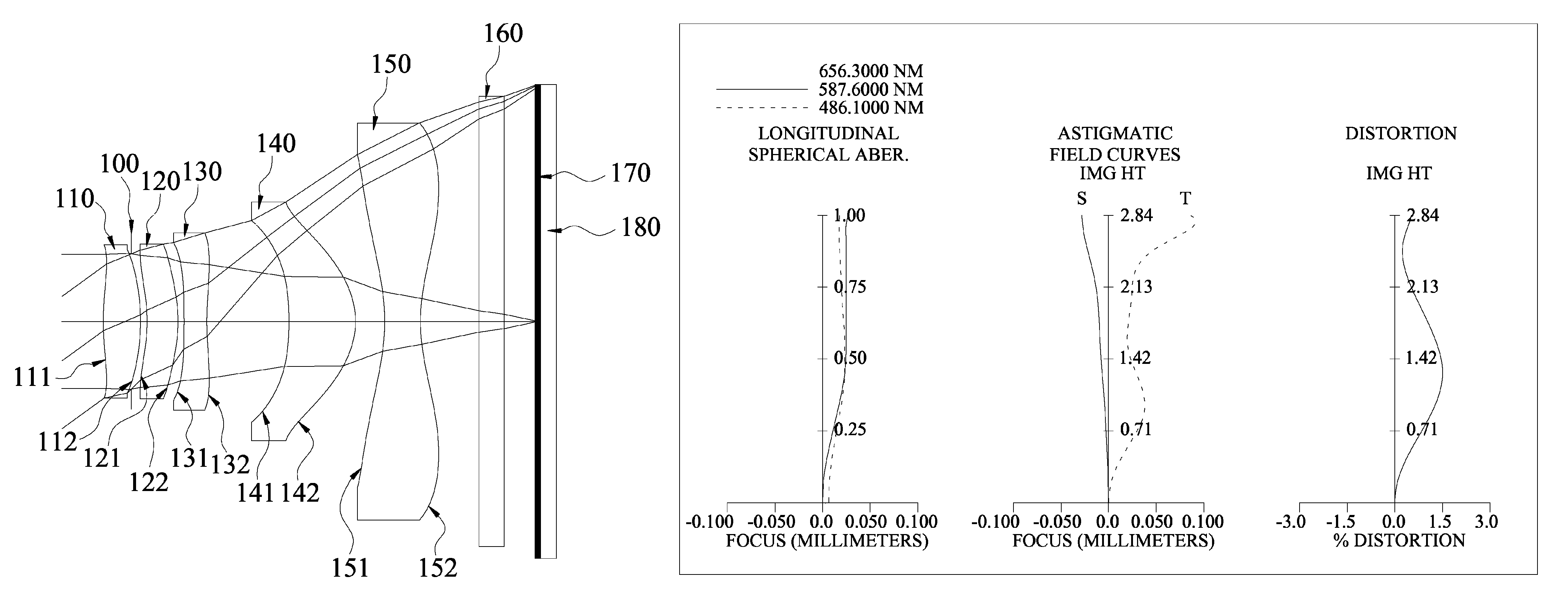
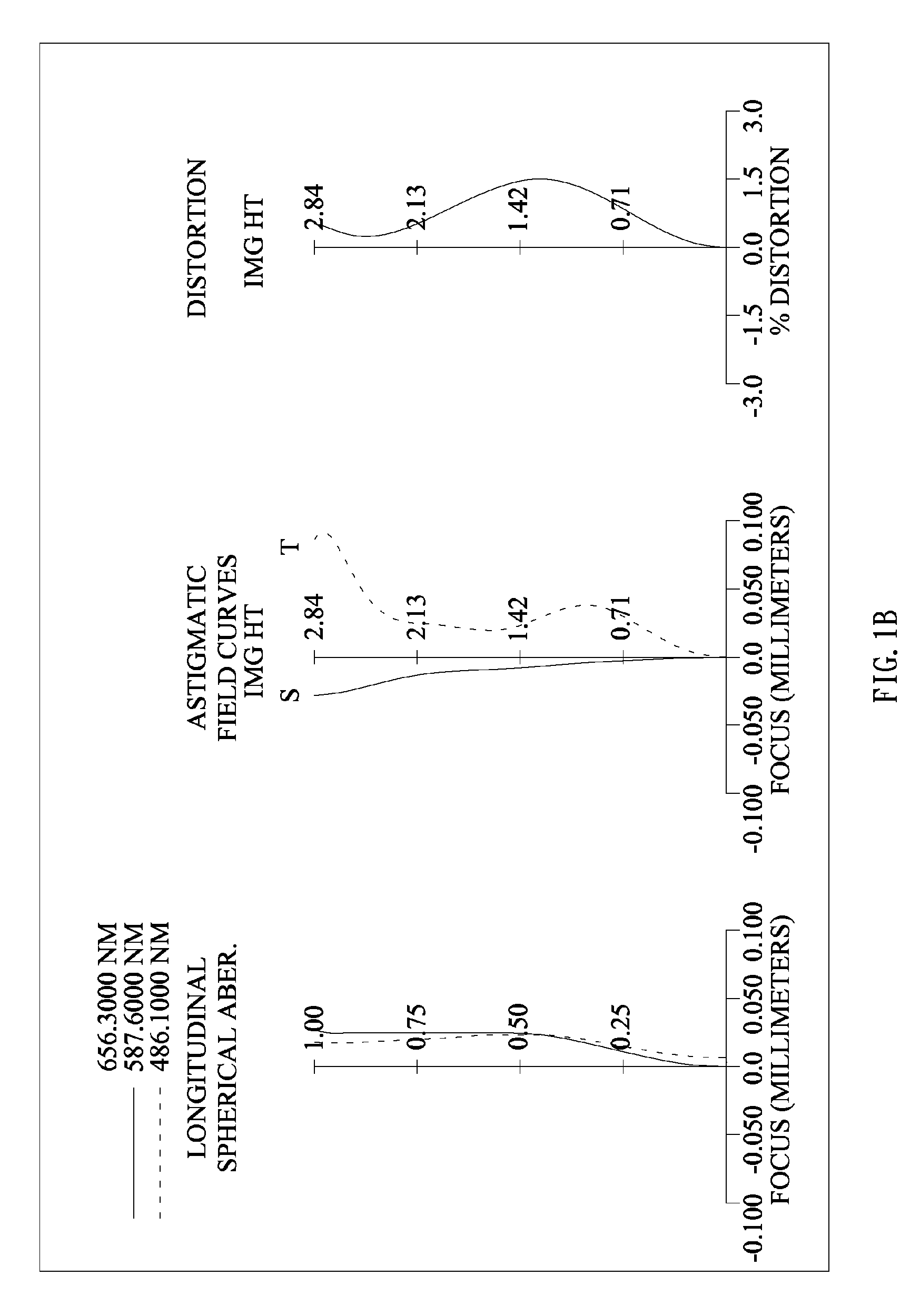
[0077]With reference to FIG. 1A, the present invention provides an imagery optical system, sequentially arranged from an object side to an image side along the optical axis comprises: the first lens element (110), the second lens element (120), the third lens element (130), the fourth lens element (140) and the fifth lens element (150), wherein the first lens element (110) with positive refractive power has a convex object-side surface (111) and a convex image-side surface (112) proximate to the optical axis, and each of the object-side surface (111) and image-side surface (112) can be aspheric or spheric; the second lens element (120) with positive refractive power has a convex image-side surface (121) proximate to the optical axis, and each of the object-side surface (121) and image-side surface (122) can be aspheric or spheric; the third lens element (130) with negative refractive power has a concave image-side surface (132) proximate to the optical axis, and each of the object-s...


PUM


Abstract

An imagery optical system, sequentially from an object side to an image side on an optical axis comprising: the first lens element with positive refractive power, the second lens element with positive refractive power, the third lens element, the fourth lens element, and the fifth lens element having at least one inflection point. Each of the five lens elements may be made of plastic and comes with bi-aspheric surfaces. The imagery optical system satisfies conditions related to shorten the total length and to reduce the sensitivity for use in compact cameras and mobile phones with a camera function.

Description

BACKGROUND OF THE INVENTION[0001]1. Field of the Invention[0002]The present invention relates to an imagery optical system, and more particularly to a low-priced optical lens assembly with five lens elements constituting the total length of the optical lens assembly and the imagery optical system is applied to an electronic product.[0003]2. Description of the Related Art[0004]As science and technology advance, the development of electronic products such as digital still cameras, web cameras and mobile phone cameras tends to have a compact design to meet the user requirements for an optical lens assembly with good aberration correction ability, high resolution, and high image quality, in addition to the compact and low-cost requirements.[0005]In general, a conventional optical lens assembly of a mini electronic product comes with different designs, including two-lens, three-lens, four-lens, and five-or-more lens designs. If the image quality is taken into consideration, the optical l...

Claims


Application Information

Patent Timeline
Patent Type & Authority Patents(United States)
IPC IPC(8): G02B9/60G02B13/18G02B3/02
CPCG02B9/60G02B13/0045G02B13/18
Inventor TSAI, TSUNG-HANHUANG, HSIN-HSUAN
Owner LARGAN PRECISION
Learn More