Microprobe, measurement system and method

a microprobe and measurement system technology, applied in the field of microprobes, can solve the problems of inability to measure the roughness or form of the channel sidewall, the nozzle of inkjet printers, the inability to measure the roughness and form of the channel, and the inability to meet the needs of inkjet printers, etc., and achieve the effect of high accuracy and precise control of the probe's activity

Inactive Publication Date: 2013-07-09
THE UK SEC FOR INNOVATION UNIVERSITIES & SKILLS OF HER MAJESTYS BRITANNIC GOVERNMENT
View PDF7 Cites 3 Cited by
  • Summary
  • Abstract
  • Description
  • Claims
  • Application Information

AI Technical Summary

Benefits of technology

[0029]The microprobe may vibrate or oscillate the probe tip to form a virtual probe tip. Interactions between the virtual probe tip and a surface or other artefact to be measured can be detected by the sensors. By keeping the probe tip and stem relatively stiff (sufficiently stiff that the probe stem does not bend due to the vibration) the present invention seeks to provide precise control over what the probe is doing. Additionally, by the use of multiple flexures preferably 3, multi-axis operation is possible, something which is lacking in many prior art microprobe implementations.
[0030]Embodiments of the present invention provide a miniature, high accuracy, contacting element capable of making measurements of high aspect ratio features such as those typically found on MEMS type components. The probe element consists of a flexure structure with integrated sensing and actuating elements, supporting a ball-ended probe stylus. It will be appreciated that the stylus need not necessarily be ball-ended (or have any different end shape at all).
[0031]Application of appropriate drive signals to the actuating elements causes the probe tip to oscillate in a defined path, creating a virtual probe tip in 1, 2 or three dimensions. Interaction of the virtual probe tip with a surface will produce a change in the output signals from the flexure sensing elements, with subsequent interpretation of the signals providing information on probing force and contact direction. Preferably, the probe element will be packaged in such a way so as to make it compatible with commercially available micro-CMM systems.
[0032]Embodiments of the present invention when implemented as a vibrating probe may additionally provide the following benefits:
[0044]The proposed probe is expected to significantly reduce testing costs and avoid destroying structures to be tested / analysed.

Problems solved by technology

For example, items such as the nozzles from inkjet printers, injector holes for diesel engines and the like are becoming increasingly complex and increasingly small.
However, with the increasing reduction in size of the channels, conventional technology is no longer appropriate for measuring roughness and form.
However, whilst these systems can measure the diameter and depth of the channel, they cannot measure the roughness or form of the channel's sidewalls.
For example, if scalloping exists from production of the channel, such systems are unlikely to identify this.
Another known technique is destructive testing in which the object is chopped in two and measured from the side.
Whilst this does enable all the necessary characteristics to be measured, it is exceptionally expensive and also results in destruction of the object being measured.
This currently costs upwards of £10,000 per wafer which, for anything but a major product, is too high and often means such testing is skipped.
As such, conventional CMMs are not particularly applicable to use on objects of millimeter or sub-millimeter scale and indeed cannot normally be calibrated to a level of accuracy required for measuring such objects.
Whilst there have been attempts made to reduce the size of CMMs, one particular complication that has arisen is that when they are reduced in scale, the conventional probe and probe tip typically becomes too thin to be useful as a contact sensing measuring device.
There is a lack of suitable metrology solutions for measurement of high aspect ratio micro-scale components.
There are commercially available probes, but as they operate in a de mode or vibrate in one axis only their measurement versatility is limited and they can suffer from low speeds stiction, high probing forces and contamination.
Whilst such systems avoid the issue of the probe being too thin to enable accurate force feedback measurements, their implementations are somewhat limited due to the complex manner in which interactions with the oscillating rod are measured.

Method used


Image

  • Microprobe, measurement system and method
  • Microprobe, measurement system and method
  • Microprobe, measurement system and method

Examples


Embodiment Construction

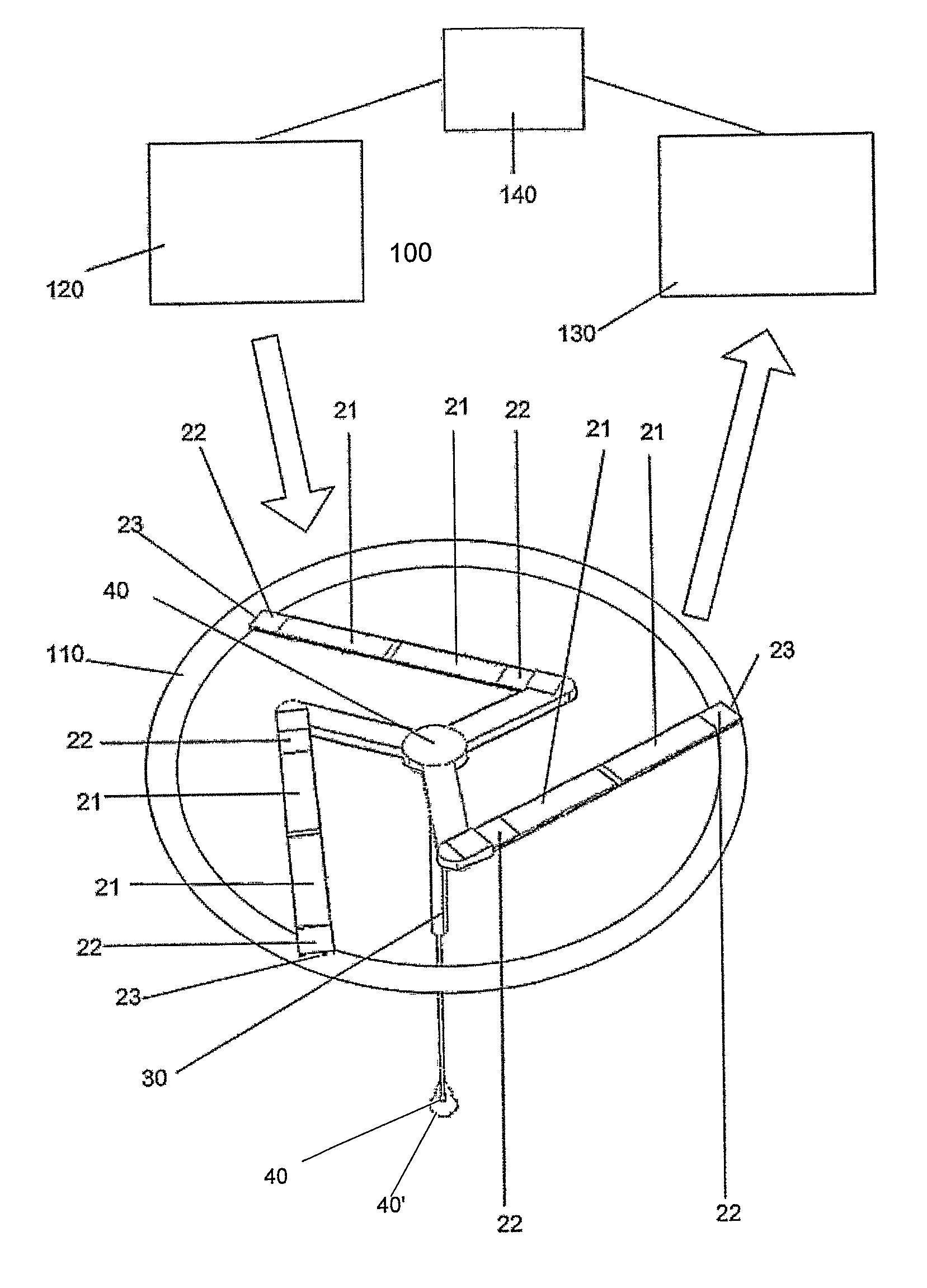
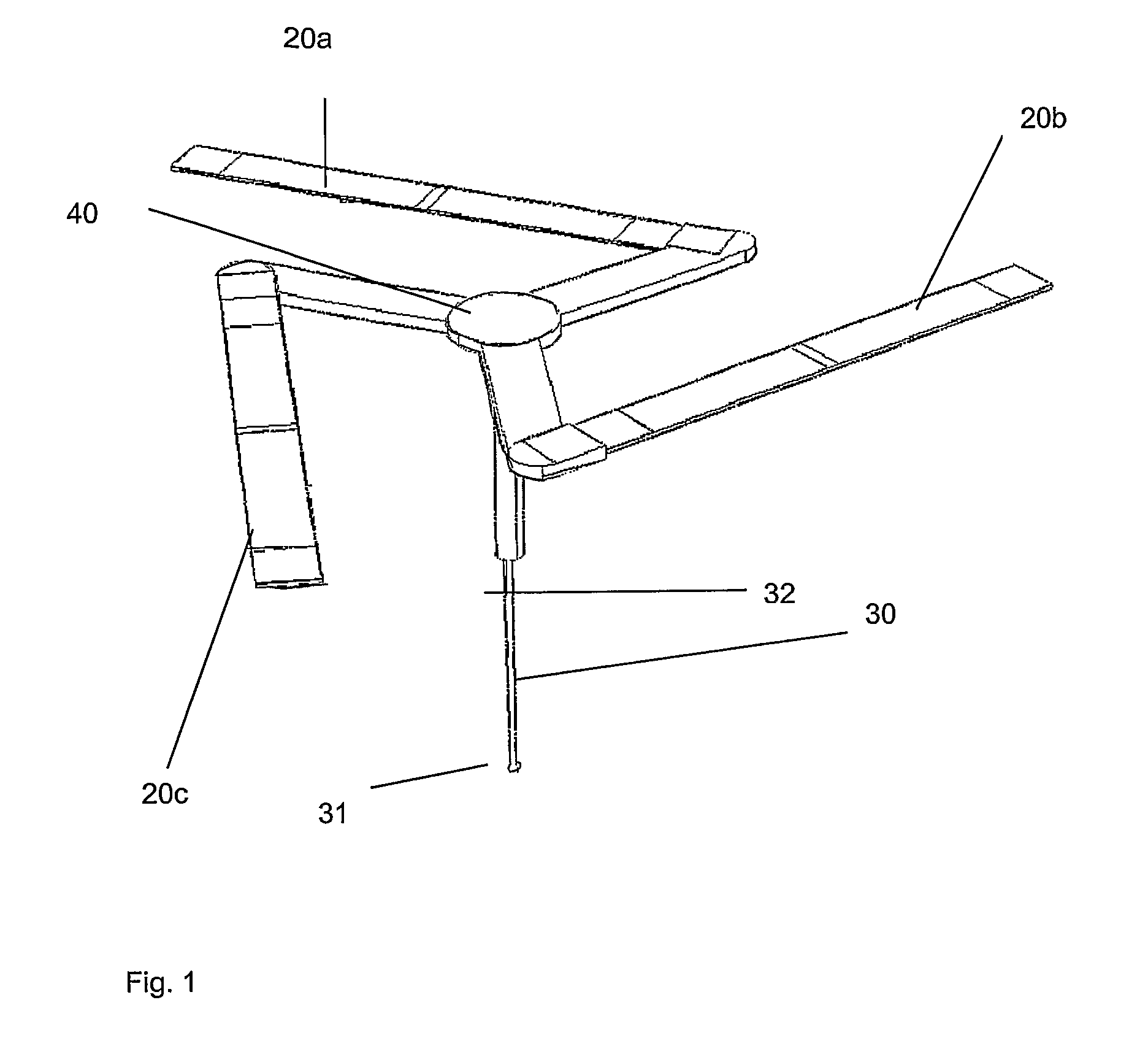
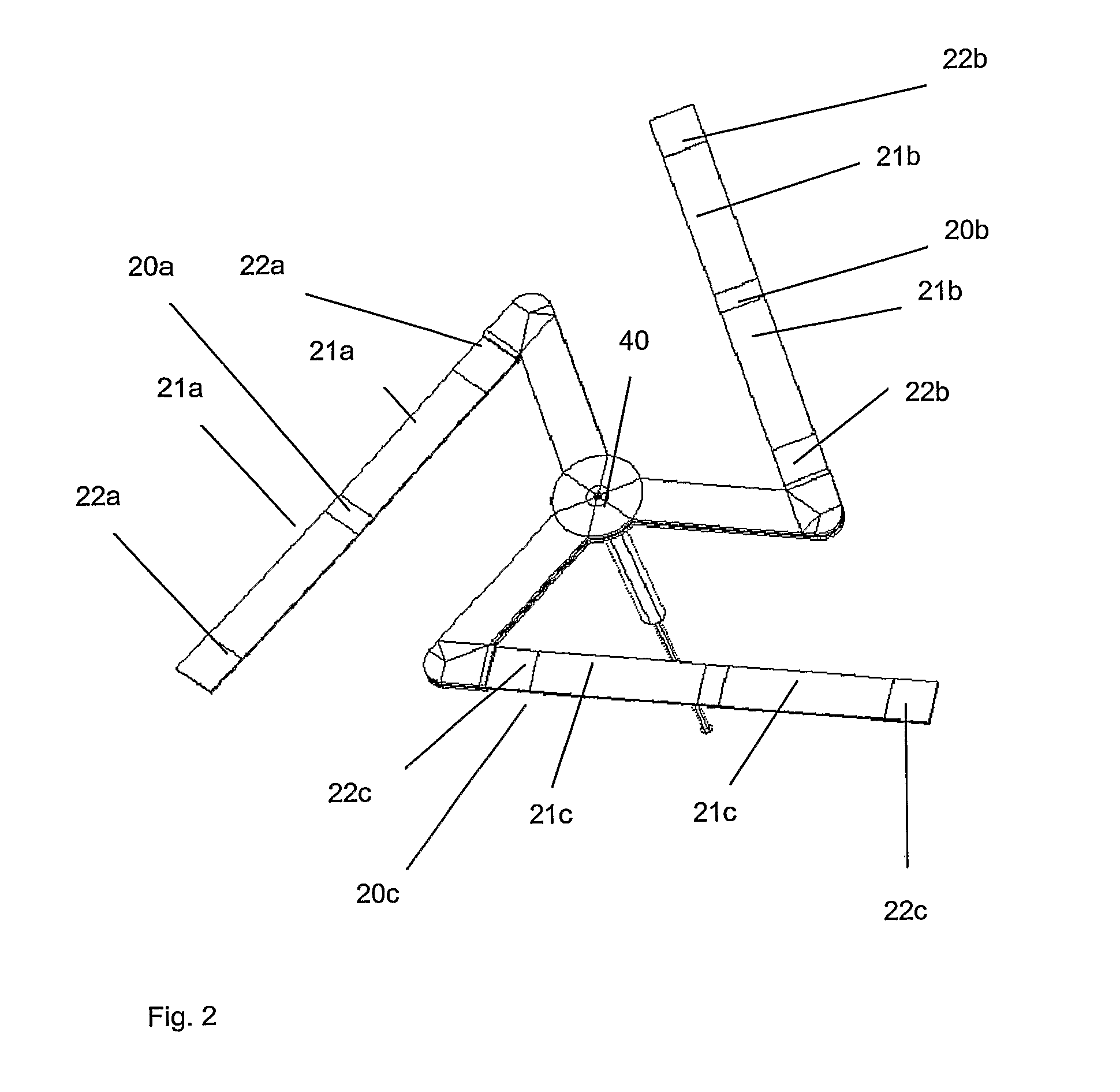
[0050]FIGS. 1 and 2 are perspective views of a microprobe according to an embodiment of the present invention.

[0051]The microprobe 10 includes a plurality of flexures 20a, 20b, 20c and a probe 30. The flexures are aligned in a plane and meet at a point 40 at which the probe 30 is connected.

[0052]Each flexure 20a, 20b, 20c includes at least one actuator 21a, 21b, 21c and at least one sensor 22a, 22b, 22c.

[0053]It will be appreciated that the number of actuators and sensors per flexure may vary. In the preferred embodiment illustrated in FIG. 1, there are two actuators interposed between two sensors per flexure, one of the sensors being positioned on or in the flexure at a point adjacent the meeting point 40 at which the probe 30 is connected and the other being on or in the flexure adjacent a free end of the flexure 23.

[0054]Preferably, both the actuator and sensor are piezo-electric elements.

[0055]The piezo-electric elements may be of a piezo-electric material such as PZT (lead zir...


PUM


Abstract

A microprobe, measurement system and method are disclosed. The microprobe includes a probe tip mounted at a meeting point of a plurality of flexures. The probe tip is moveable upon flexing of one or more of the flexures, each flexure further comprising one or more actuators controllable to flex the flexure and one or more sensors arranged to sense flexing of the flexure.

Description

CROSS REFERENCE TO REALATED APPLICATIONS[0001]This patent application is a National Stage Application under 35 U.S.C. 371 of Application No. PCT / GB2008 / 003846, filed on Nov. 17, 2008, which claims benefit of Great Britain Application Serial No. 0722477.7, filed Nov. 15, 2007, which are hereby Incorporated by reference in there entirety herein.FIELD OF THE INVENTION[0002]The present invention relates to a microprobe that is particularly applicable for use in co-ordinate measurement to a high degree of accuracy of feature on objects of millimeter or smaller sizes.BACKGROUND TO THE INVENTION[0003]There is a continuing desire within industry to reduce object sizes yet maintain a high degree of accuracy for those objects and features of those objects.[0004]For example, items such as the nozzles from inkjet printers, injector holes for diesel engines and the like are becoming increasingly complex and increasingly small. It is important that the channels that define the nozzles, holes and ...

Claims


Application Information

Patent Timeline
Patent Type & Authority Patents(United States)
IPC IPC(8): G01Q20/00G01Q20/04G01Q70/08
CPCB82Y35/00G01B7/002G01Q70/08G01Q10/045G01Q20/04G01B7/012G01B21/00G01Q10/00G01Q20/00G01Q30/00
Inventor LEACH, RICHARDHUGHES, BENWILSON, ALAN
Owner THE UK SEC FOR INNOVATION UNIVERSITIES & SKILLS OF HER MAJESTYS BRITANNIC GOVERNMENT
Why Eureka
Try Eureka