
Silicon controlled rectifier modeling

a rectifier and silicon technology, applied in the field of circuit models, can solve the problems of b>6/b> losing much of the physical representation of scr b>2/b>, unable to extend to a four-terminal scr model, and b>8/b> remaining difficult to characteriz

Inactive Publication Date: 2013-07-16
GLOBALFOUNDRIES INC
View PDF20 Cites 3 Cited by
  • Summary
  • Abstract
  • Description
  • Claims
  • Application Information

AI Technical Summary

Benefits of technology

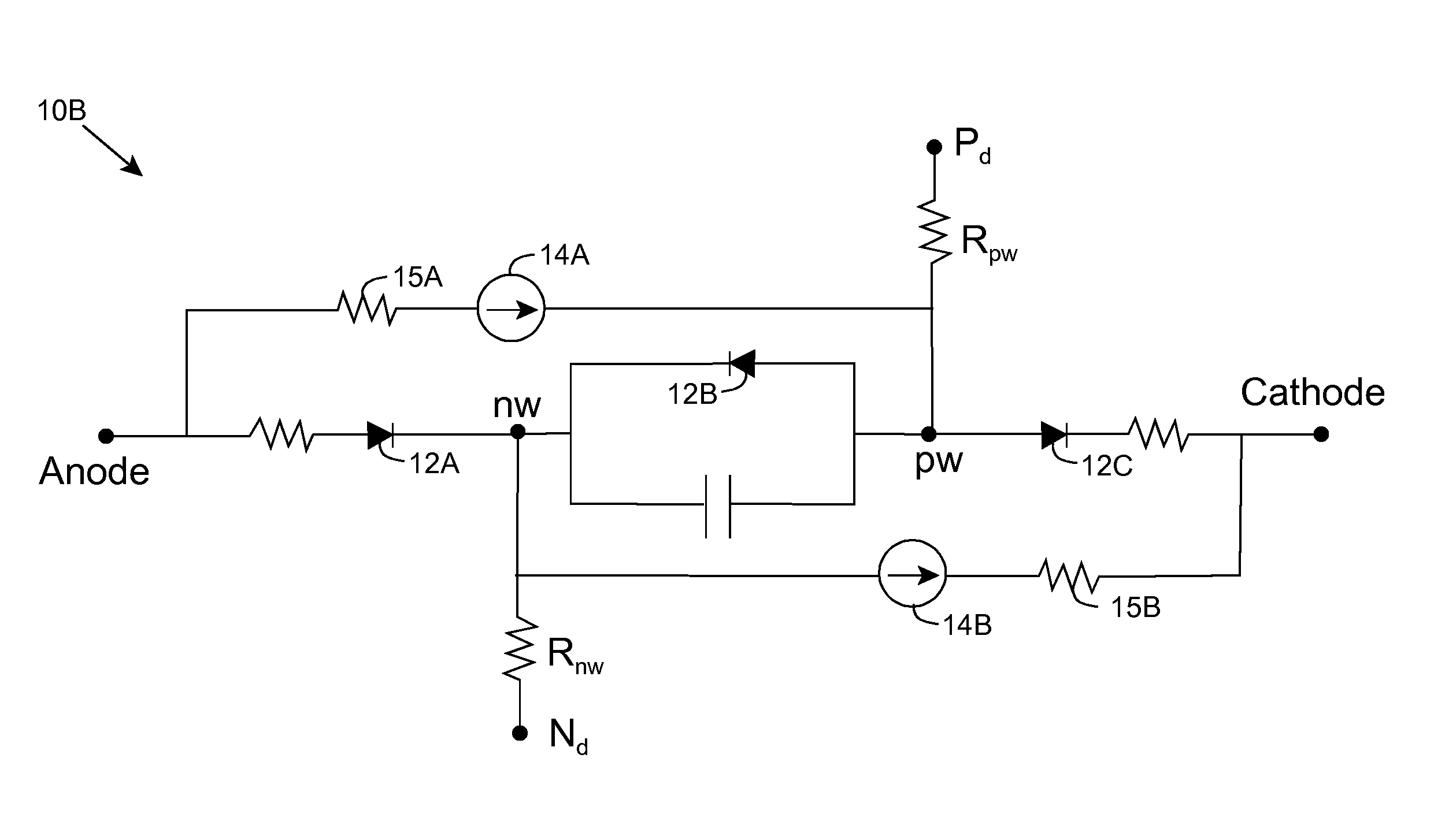
The invention provides a model for a silicon controlled rectifier (SCR) that can be used to evaluate and analyze the behavior of circuits that include the SCR. The model includes a unique diode model for each junction in the SCR, which can be adjusted based on measured data to accurately simulate the behavior of the SCR. The model can be used to evaluate the performance of the SCR in protecting against electrostatic discharge and to design and optimize circuit configurations that use the SCR.

Problems solved by technology

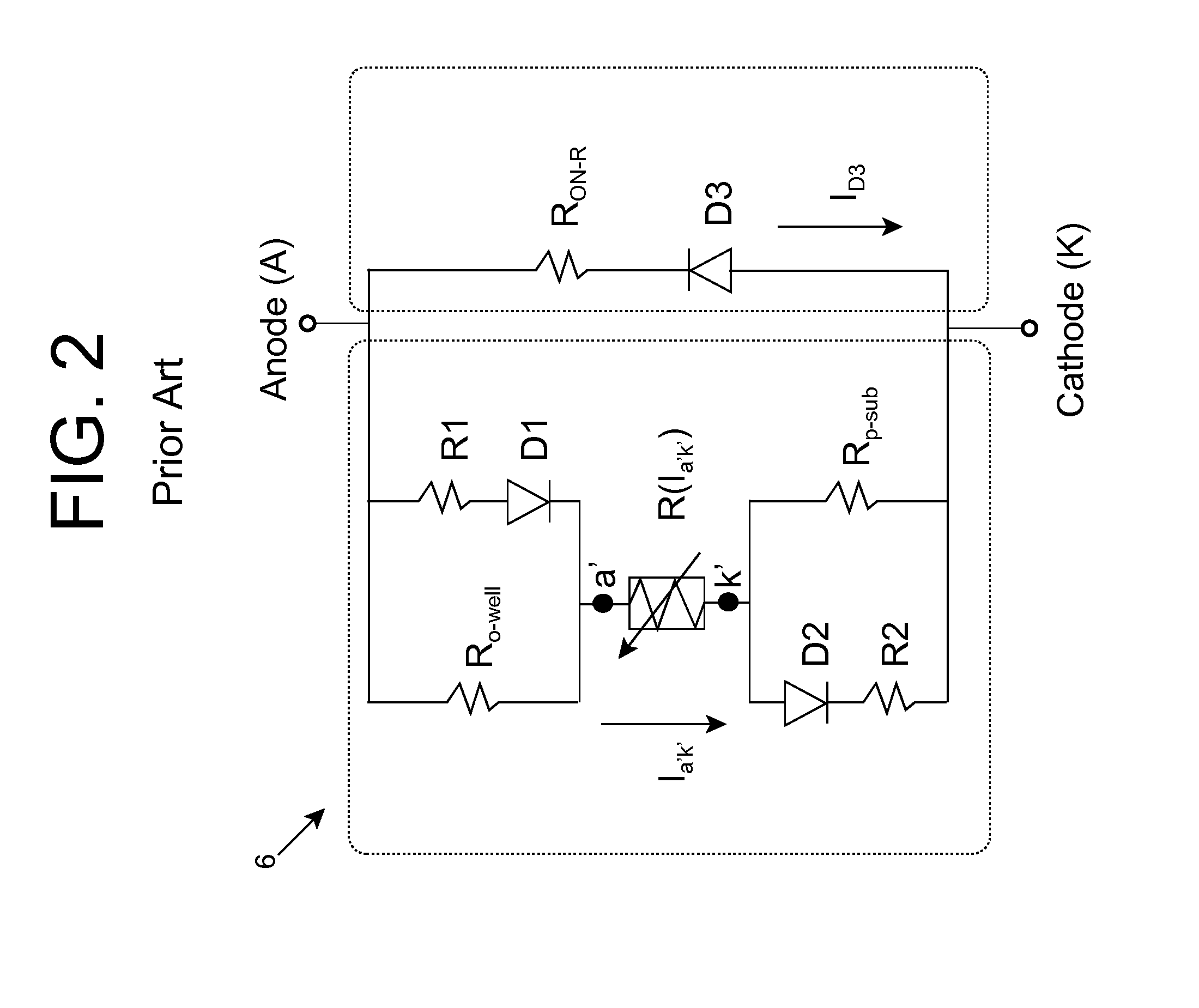
However, model 6 loses much of the physical representation of SCR 2, and cannot be extended to a four terminal SCR model.
While model 8 accurately represents the physical aspects of SCR 2 and includes four terminals, model 8 remains difficult to characterize and parameter extraction is more difficult than model 6.
The complexity of the model also brings in convergence problems during simulation.

Method used


Image

  • Silicon controlled rectifier modeling
  • Silicon controlled rectifier modeling
  • Silicon controlled rectifier modeling

Examples


Embodiment Construction

[0024]As indicated above, aspects of the invention provide a model for a silicon controlled rectifier, which includes three diode models connected in series, with the middle diode model being reverse biased. Each diode model corresponds to and can be configured to simulate DC operation of a junction in the silicon controlled rectifier. The model can be used to evaluate behavior of a circuit that includes the silicon controlled rectifier. For example, the circuit can include an electrostatic discharge protection circuit that includes the silicon controlled rectifier. As used herein, unless otherwise noted, the term “set” means one or more (i.e., at least one) and the phrase “any solution” means any now known or later developed solution.

[0025]The model captures the snapback and high current turn-on characteristics of an SCR. An embodiment of the new model comprises a physics-based model structure, and can enable reduced measurement and parameter extraction efforts over previously prop...


PUM


Abstract

A model for a silicon controlled rectifier includes three diode models connected in series, with the middle diode model being reverse biased. Each diode model corresponds to and can be configured to simulate DC operation of a junction in the silicon controlled rectifier. The model can be used to evaluate behavior of a circuit that includes the silicon controlled rectifier. For example, the circuit can include an electrostatic discharge protection circuit that includes the silicon controlled rectifier.

Description

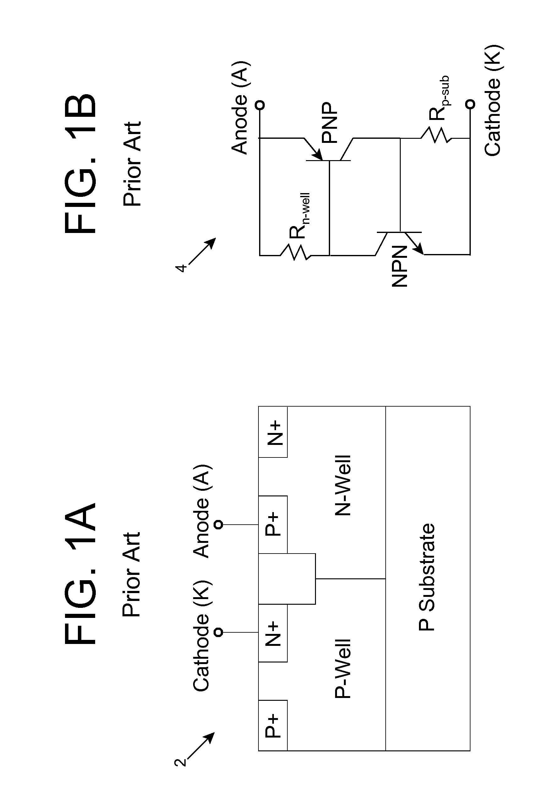
TECHNICAL FIELD[0001]The disclosure relates generally to circuit models (e.g., design structures), and more particularly, to a model for a silicon controlled rectifier.BACKGROUND ART[0002]A silicon controlled rectifier (SCR) is often used as an electrostatic discharge (ESD) protection device for a circuit. In this case, during normal operation of the circuit, the SCR is in an off state with a very high resistance. As a result, only leakage current passes through the SCR. However, after a sufficient voltage (i.e., a snapback trigger voltage) is applied, e.g., due to an ESD event, the SCR transitions to a low resistance state and begins conducting current, thereby facilitating the discharge of the current away from the other components in the circuit. A typical SCR is a PNPN device that includes two coupled bipolar transistors. FIGS. 1A and 1B show an illustrative SCR 2 and circuit diagram 4 of SCR 2 according to the prior art.[0003]Various types of SCRs 2 have been developed for ESD ...

Claims


Application Information

Patent Timeline
Patent Type & Authority Patents(United States)
IPC IPC(8): G06F9/455G06F17/50G05F1/613H02M7/10
CPCG06F17/5036G06F30/367
Inventor LI, JUNJUNNAYAK, RAHUL
Owner GLOBALFOUNDRIES INC
Learn More