
Image control device and image display system for generating an image to be displayed from received imaged data, generating display information based on the received image data and outputting the image and the display information to a display

a control device and image technology, applied in static indicating devices, instruments, editing/combining figures or texts, etc., can solve problems such as image quality degradation, inaccurate features cannot be extracted, and generated display images may involve faults that cannot be corrected, etc., to achieve the effect of processing load

Inactive Publication Date: 2013-07-23
SOVEREIGN PEAK VENTURES LLC
View PDF12 Cites 0 Cited by
  • Summary
  • Abstract
  • Description
  • Claims
  • Application Information

AI Technical Summary

Benefits of technology

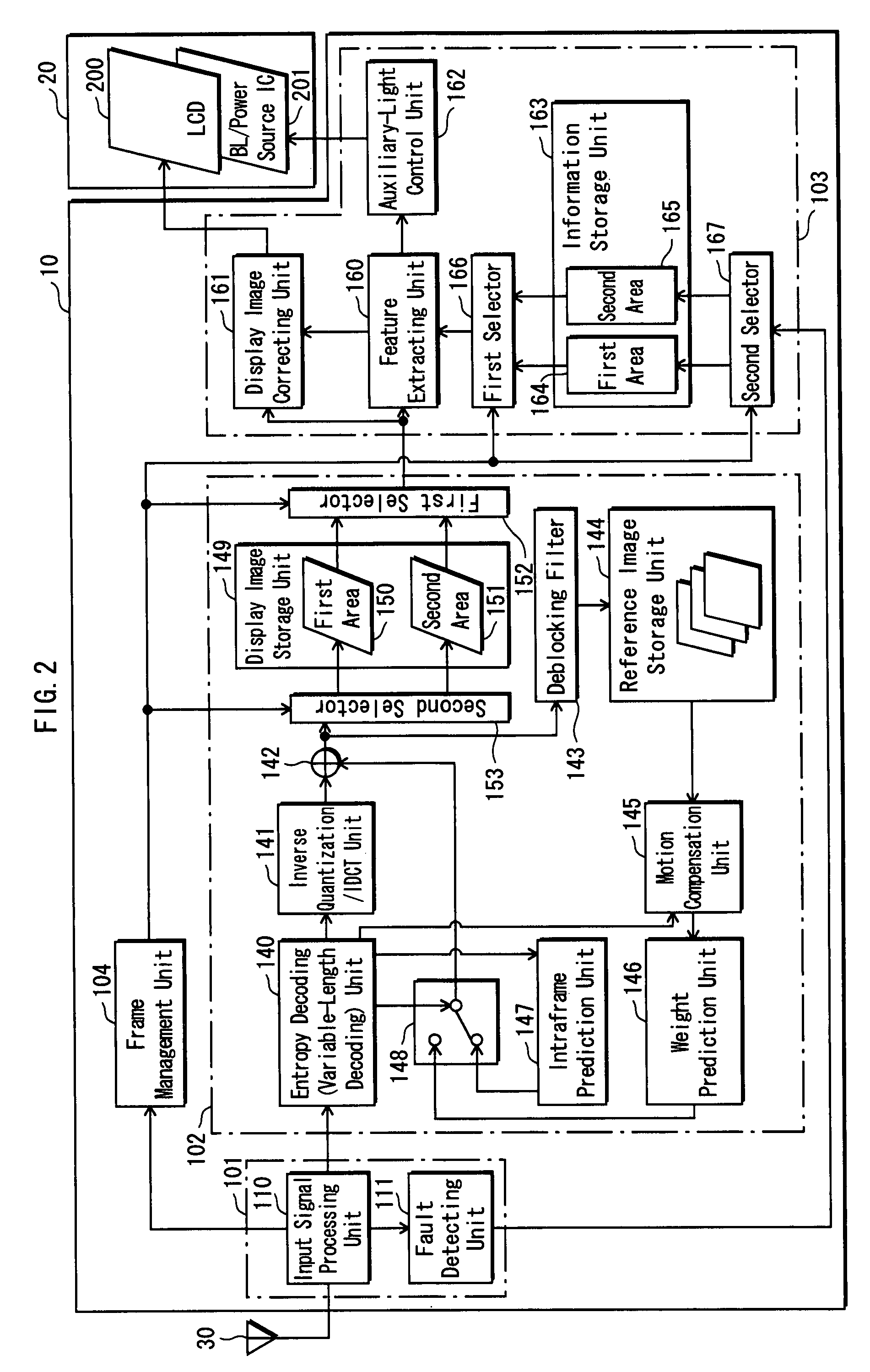
[0017]With the above configuration, the image control device does not use any fault image regions for the feature extraction, so that accurate display information is generated. Thus, the image control device prevents degradation of display images and also prevents loss of energy saving effect, even if the display image contains one or more faults.
[0050]With the above configuration, the image control device does not extract a feature from the entire region of image data, so that the processing load that would otherwise be imposed for the feature extraction is reduced.

Problems solved by technology

That is to say, the generated display images may involve faults remain uncorrected.
Thus, accurate features cannot be extracted.
This may cause that the image quality is notably degraded or that the light source intensity is uselessly increased to cancel out the power savings.
In addition, since the feature extraction is conducted on an entire region of each display image, the processing load is relatively heavy.
In addition, if the display image involves a fault, the correction cannot be carried out appropriately.

Method used


Image

  • Image control device and image display system for generating an image to be displayed from received imaged data, generating display information based on the received image data and outputting the image and the display information to a display
  • Image control device and image display system for generating an image to be displayed from received imaged data, generating display information based on the received image data and outputting the image and the display information to a display
  • Image control device and image display system for generating an image to be displayed from received imaged data, generating display information based on the received image data and outputting the image and the display information to a display

Examples


first embodiment

1. First Embodiment

[0078]The following describes an image display system 1 according to a first embodiment of the present invention.

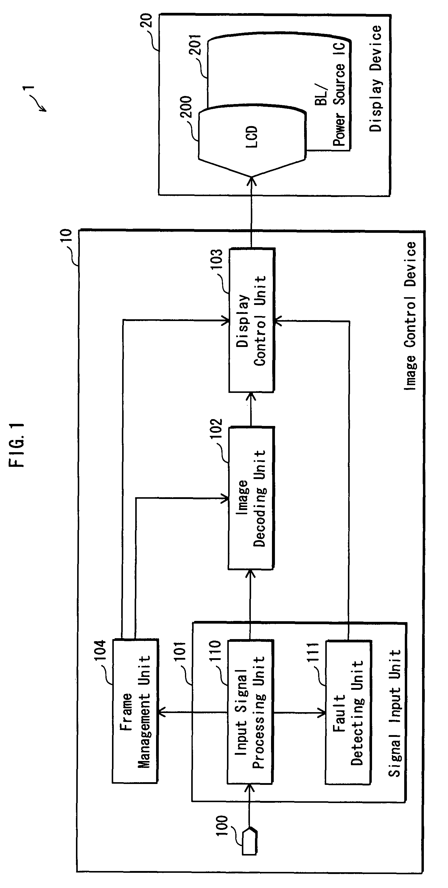
[0079]As illustrated in FIG. 1, the image display system 1 is generally composed of an image control device 10 and a display device 20.

[0080]The image control device 10 receives an image signal (image data) from the outside, generates a display image from the received image signal, and outputs the generated display image to the display device 20, along with a correction value of the display image and an intensity value of auxiliary light to be emitted. The correction value is a luminance value at which the display image is to be displayed. In the following description, a display image may also be referred to as a frame.

[0081]The display device 20 is generally composed of an LCD (Liquid Crystal Display) 200 and a BL (backlight) / power source IC 201. The display device 20 receives a display image from the image control device 10 along with a correction val...

second embodiment

2. Second Embodiment

[0168]The following describes an image display system 2 according to a second embodiment of the present invention, focusing on differences with the first embodiment.

[0169]As illustrated in FIG. 8, the image display system 2 is generally composed of an image control device 1010 and a display device 1020.

[0170]The image control device 1010 differs from the image control device 10 with respect to the following. The image control device 10 conducts the fault detection only at the time of image signal input, where as the image control device 1010 additionally conducts the fault detection at the time of image decoding.

[0171]As illustrated in FIGS. 8 and 9, the display device 1020 is generally composed of an LCD 1200 and a BL / power source IC 1201. The LCD 1200 and the BL / power source IC 1201 are respectively identical to the LCD 200 and the BL / power source IC 201 described in the first embodiment. Thus, no further description is given here.

[0172]The following describes ...

third embodiment

3. Third Embodiment

[0287]The following describes an image display system 3 according to a third embodiment of the present invention, focusing on differences with the second embodiment.

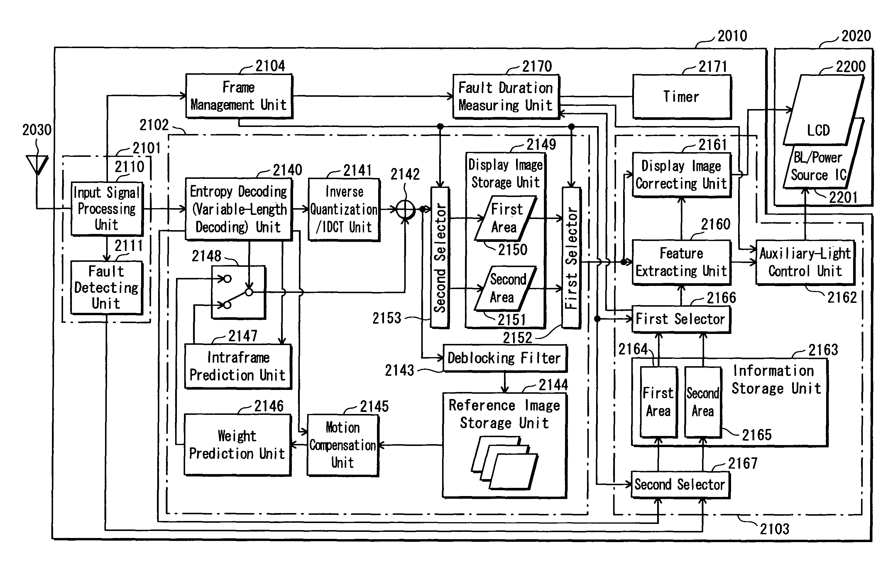
[0288]As illustrated in FIG. 18, the image display system 3 is generally composed of an image control device 2010 and a display device 2020.

[0289]The image control device 2010 differs from the image control device 1010 with respect to the following. The image control device 2010 starts measuring time upon detection of a fault in a display image and ends the time measurement upon reception of a normal display image (a display image in which no fault is detected). The image control device 2010 conducts display image control in accordance with the measurement result.

[0290]As illustrated in FIGS. 18 and 19, the display device 2020 is generally composed of an LCD 2200 and a BL / power source IC 2201. The LCD 2200 and the BL / power source IC 2201 are respectively identical to the LCD 1200 and the BL / power sourc...


PUM


Abstract

An image control device, which achieves energy saving effects without degradation of an image to be displayed, even if image data includes a fault, is configured to decode received image data into an image, generate display information based on the received image data, and output a decoded image and display information. The image control device receives image data, detects errors from the image data. For each error detected, the image control device specifies a fault image region containing an error from an entire image region of the image data, and inhibits use of the fault image region for generating display information that defines an image display condition according to which the display device performs the image display.

Description

[0001]This application is based on an application No. 2006-143843 filed in Japan, the content of which is hereby incorporated by reference.BACKGROUND OF THE INVENTION[0002](1) Field of the Invention[0003]The present invention relates to a device and method for controlling image display. The present invention especially relates to a display control technique for use by an image display apparatus that displays images by casting light from a light source onto a reflection-type display device, typified by an liquid crystal panel. According to the display control technique, the light source intensity is dynamically adjusted in relation to the correction of display image contents.[0004](2) Description of the Related Art[0005]The following technique is disclosed regarding an image display apparatus that displays images on a liquid crystal panel. According to the disclosure, pixel data is attached with an error-detecting bit and an image display apparatus detects and corrects any errors in ...

Claims


Application Information

Patent Timeline
Patent Type & Authority Patents(United States)
IPC IPC(8): G09G5/00G06T11/40G06T11/60G06T15/30
CPCG09G5/397G06T15/30G06T11/60H04N19/91H04N19/44H04N19/42H04N19/89H04N19/423G06T11/40G09G3/3648G09G2320/0247G09G2330/021G09G2330/08G09G2340/02
Inventor KIMURA, TOMOOHATA, RYOUTA
Owner SOVEREIGN PEAK VENTURES LLC
Learn More