Separation column for liquid chromatograph apparatus and liquid chromatograph apparatus using thereof

a liquid chromatograph and separation column technology, applied in the direction of separation processes, instruments, ion-exchangers, etc., can solve the problems of degrading separation performance, difficult to find a material satisfying such conditions, and difficult to form a porous body with high precision, etc., to achieve high pressure resistance

Inactive Publication Date: 2013-07-30
HITACHI HIGH-TECH CORP
View PDF9 Cites 3 Cited by
  • Summary
  • Abstract
  • Description
  • Claims
  • Application Information

AI Technical Summary

Benefits of technology

[0012]According to the present invention, both a column having high-pressure resistance and capable of performing high-speed separation and analysis even with a small flow rate and a liquid chromatograph apparatus using the column can be provided.

Problems solved by technology

Therefore, it is very difficult to form a porous body with high precision such that the outside diameter of a cross section thereof is constant along the length direction.
It is difficult to find a material satisfying such conditions.
Thus, a volatile solvent in the resin cladding material is eluted, degrading separation performance.

Method used


Image

  • Separation column for liquid chromatograph apparatus and liquid chromatograph apparatus using thereof
  • Separation column for liquid chromatograph apparatus and liquid chromatograph apparatus using thereof
  • Separation column for liquid chromatograph apparatus and liquid chromatograph apparatus using thereof

Examples


Embodiment Construction

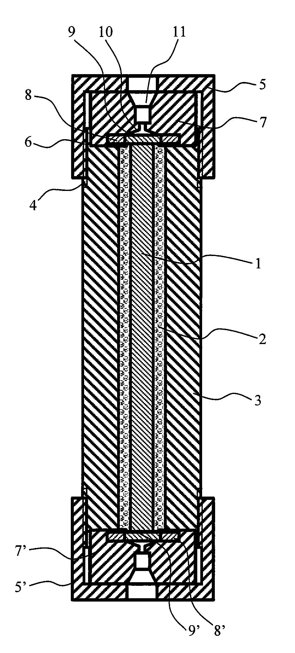
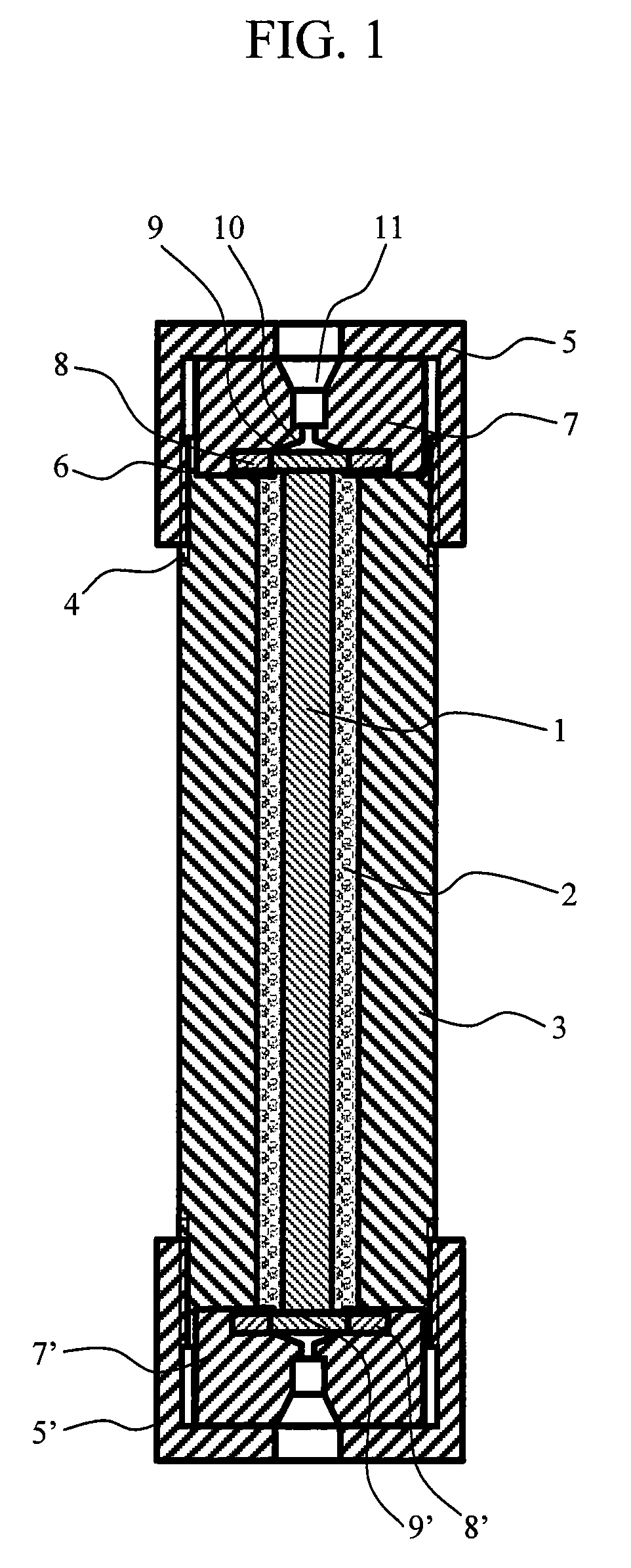
[0034]The configuration of a separation column according to the present invention will be described with reference to FIG. 1. The separation column in the present embodiment has a separation column part in the center, an upstream connection part on an upstream side thereof, and a downstream connection part on a downstream side thereof. The separation column part has a monolithic rod 1 being arranged in the center and having a circular cross section, a tube-like filler layer 2 outside thereof, and a cylindrical support medium 3 on the outermost side. The monolithic rod 1, the filler layer 2, and the support medium 3 are concentrically arranged and have the same length in the axial direction. The filler layer 2 is formed by filling a tube-like gap between the support medium 3 and the monolithic rod 1 with particles or beads.

[0035]The upstream connection part has a circular filter 9, a ring-shaped sealant 8, a columnar connection member 7, and a cup-shaped fixing member 5. The filter 9...


PUM

PropertyMeasurementUnit
diameteraaaaaaaaaa
diameteraaaaaaaaaa
lengthaaaaaaaaaa

Abstract

Both a column having high-pressure resistance and capable of performing high-speed separation and analysis even with a small flow rate and a liquid chromatograph apparatus using the column are provided. A separation column according to the present invention has a monolithic rod being arranged in the center, being made of a porous material, and having a circular cross section, a filler layer arranged such that it encircles a circumferential surface of the monolithic rod, and a cylindrical support medium arranged outside the filler layer. The filler layer is formed by filling a tube-like gap between the monolithic rod and the support medium with particles or beads.

Description

BACKGROUND OF THE INVENTION[0001]1. Field of the Invention[0002]The present invention relates to a separation column for separating components in a liquid sample and a liquid chromatograph apparatus using thereof.[0003]2. Description of the Related Art[0004]In a high speed liquid chromatograph apparatus, a particle-filling column has been used as a column for separating components in a liquid sample. In recent years, however, a monolithic-type column is increasingly used, instead of the particle-filling column. A monolithic-type silica column, for example, is known as a monolithic-type column.[0005]A monolithic-type silica column includes a narrow tube and a porous body inserted therein. The porous body is called a monolithic rod, a monolithic silica rod or the like. The porous body is a thin rod body. Therefore, it is very difficult to form a porous body with high precision such that the outside diameter of a cross section thereof is constant along the length direction. Thus, a gap...

Claims


Application Information

Patent Timeline
Patent Type & Authority Patents(United States)
IPC IPC(8): B01D15/08G01N30/02C02F1/28
CPCB01D15/22B01J20/282G01N30/6047G01N30/6052G01N30/6069B01J2220/82B01J2220/825G01N30/22G01N2030/522G01N2030/528
Inventor SHIMIZU, KATSUTOSHIITO, MASAHITOISHII, KIMIHIKONAGAOKA, YOSHIHIRODEGUCHI, KISABUROYOKOKURA, TAKEFUMI
Owner HITACHI HIGH-TECH CORP
Why Eureka
Try Eureka