
Fluidized bed carbon dioxide scrubber for pneumatic conveying system

a technology of carbon dioxide scrubber and flue bed, which is applied in the direction of lighting and heating apparatus, furnaces, separation processes, etc., can solve the problem of not being able to remove substantially all of the carbon dioxide from the ambient air of these systems

Inactive Publication Date: 2013-07-30
NOL TEC SYST
View PDF20 Cites 1 Cited by
  • Summary
  • Abstract
  • Description
  • Claims
  • Application Information

AI Technical Summary

Benefits of technology

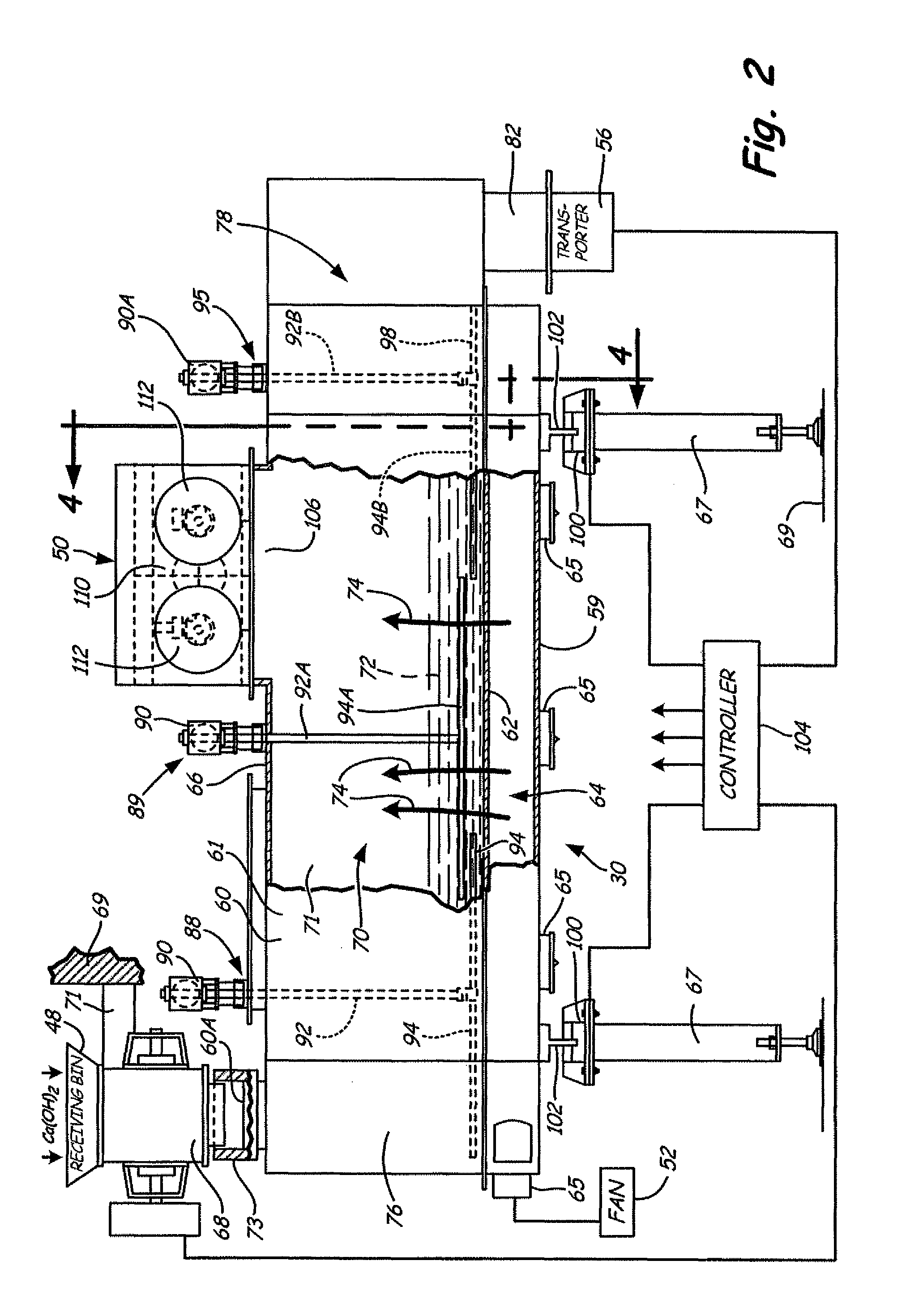
[0006]The present disclosure relates to a pneumatic conveying system that includes a scrubber or device for removing carbon dioxide from the air that is used as the carrier fluid in the pneumatic conveying system to avoid problems arising when air containing carbon dioxide is used for conveying hydrated lime (calcium hydroxide). The present unit provides a fluidized bed containing hydrated lime (calcium hydroxide), through which the ambient air to be used for pneumatic conveying is passed, to permit the carbon dioxide in the air to react with the calcium hydroxide to form calcium carbonate or limestone, and water. This scrubbing action is completed before the air is passed through a filter for removing dust and particles. The filtered, carbon dioxide free air is directed to a compressor and / or blower used in the pneumatic conveying system.

Problems solved by technology

However, the ability to remove substantially all of the carbon dioxide from ambient air has been lacking in these systems, and it is desirable to have a self-contained, carbon dioxide scrubber for all of the air that is used for pneumatically conveying hydrated lime (calcium hydroxide) to a flue gas scrubbing system.

Method used


Image

  • Fluidized bed carbon dioxide scrubber for pneumatic conveying system
  • Fluidized bed carbon dioxide scrubber for pneumatic conveying system
  • Fluidized bed carbon dioxide scrubber for pneumatic conveying system

Examples


Embodiment Construction

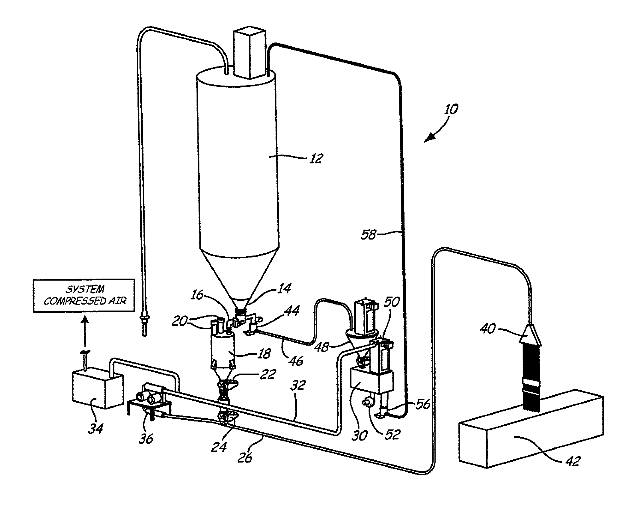
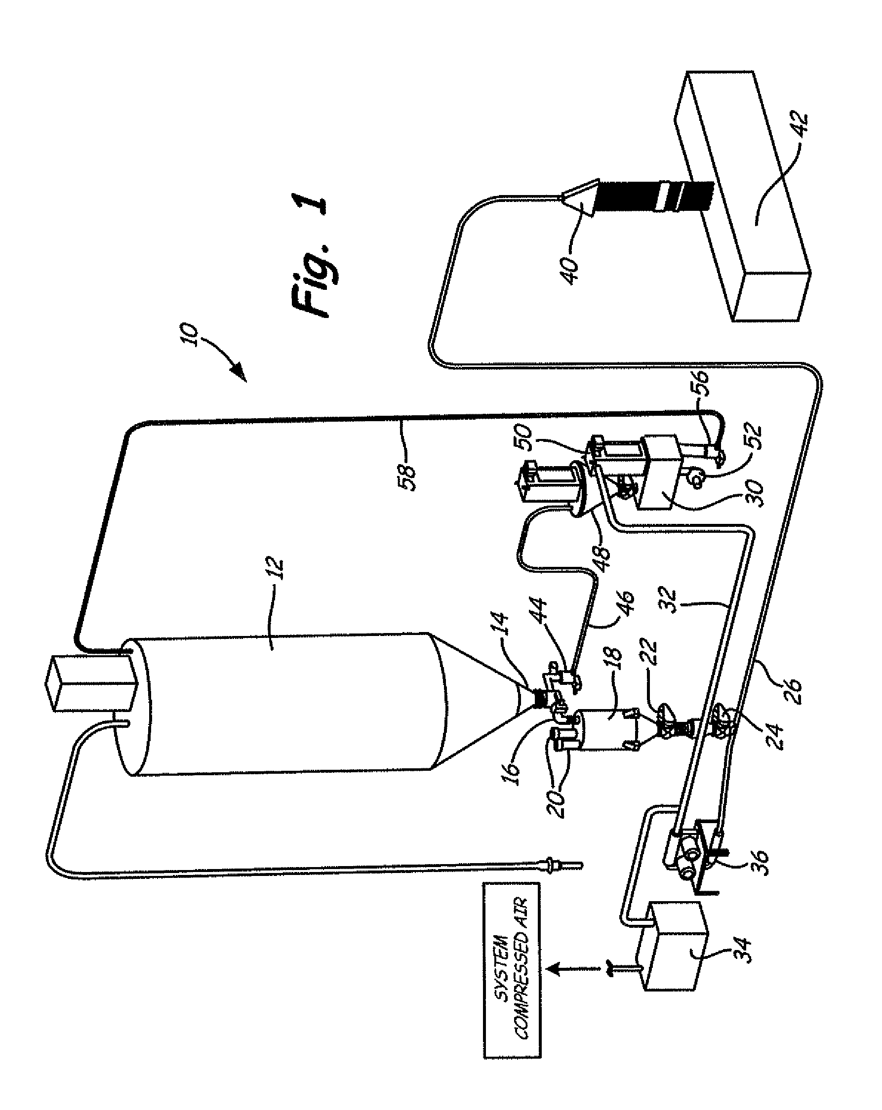
[0015]FIG. 1 shows a typical pneumatic conveying system indicated generally at 10 that is utilized for providing dry hydrated lime to a duct used in a flue gas scrubbing system, for example. The pneumatic conveying system 10 is provided with a dry particulate hydrated lime storage silo 12 of conventional design, that includes a conventional fluidizing bin bottom 14 used for dispensing material into a fluidizing conveying system. The bin bottom 14 is a valve type arrangement that will permit material in the bin to be discharged through a first conduit 16 and then through a weighing hopper 18 that is used for determining the amount of material being injected into a flue gas scrubbing system using dry hydrated lime. The weighing hopper 18 can have dust filters 20 in an upper end for permitting air to discharge and removing dust from such discharge. As shown includes two separate rotary air locks 22 and 24 are positioned to control the amount of material being fed into a line 26, to whi...


PUM

PropertyMeasurementUnit
thickaaaaaaaaaa
air permeableaaaaaaaaaa
pressureaaaaaaaaaa

Abstract

A pneumatic conveying system for conveying hydrated lime is provided with ambient air for the pneumatic conveying system from a scrubber that removes carbon dioxide from the ambient air used in the conveying system. The scrubber includes a bed of hydrated lime through which ambient air is passed, to react carbon dioxide in the air with the hydrated lime in a reaction that forms limestone and water. The air that has passed through the fluidized bed, which is essentially carbon dioxide free, is also passed through a filter to remove particles suspended in the carbon dioxide free air. The carbon dioxide free air from the filter is provided to the pneumatic conveying system. The use of carbon dioxide free air ensures that the hydrated lime being transported in the conveying system will not react in the various conduits and ducts of the pneumatic conveying system to cause problems.

Description

CROSS-REFERENCE TO RELATED APPLICATION[0001]This patent application refers to and claims priority of U.S. Provisional Application Ser. No. 61 / 308,078, filed Feb. 25, 2010, the content of which is incorporated by reference.BACKGROUND OF THE DISCLOSURE[0002]The present disclosure relates to a fluidized bed for removing carbon dioxide from atmospheric air that is used for conveying particulate materials in particular, dry particulate or powdered hydrated lime for injection into gas desulfurization systems.[0003]It is known that dry hydrated lime can be used for removing sulfur dioxide (SO2) and sulfur trioxide (SO3) from flue gasses issuing from the boilers of fossil fuel burners. The mitigating of SO2 and SO3 emissions by injecting dry powdered hydrated lime sorbent directly into a utility duct work that is seeking to reduce emissions is done by pneumatic conveying systems that convey the hydrated lime to the flue gas ducts or passageways.[0004]Using atmospheric air for the conveying ...

Claims


Application Information

Patent Timeline
Patent Type & Authority Patents(United States)
IPC IPC(8): B01D53/12B01J8/18B01D53/62
CPCB01D53/62B01D53/83B01J8/003B01J8/006B01J8/1809B01J8/1818B01J8/1827B01J8/24B01J8/382B01D53/508B01D2251/404B01D2257/504B01J2208/0061Y02C10/04Y02C10/08Y02A50/20Y02C20/40
Inventor MOONEY, MICHAEL JOHN
Owner NOL TEC SYST
Learn More