
Water heating control and storage system

a water heater and control mechanism technology, applied in the direction of heating types, heating arrangements, instruments, etc., can solve the problems of increasing the monthly energy bill of consumers, requiring a substantially different control mechanism, and adapting to period variation in the rate schedule and emergency load shedding request signals from the utility, so as to achieve the effect of reducing the operating cos

Active Publication Date: 2013-07-30
HAIER US APPLIANCE SOLUTIONS INC
View PDF14 Cites 15 Cited by
  • Summary
  • Abstract
  • Description
  • Claims
  • Application Information

AI Technical Summary

Benefits of technology

The invention is a water heating and storage system that can reduce energy costs by controlling the temperature of the tank and only heating up the necessary amount of water. This is done by using a control device that receives information about energy rates or usage from an external source or a programmed schedule. The system also includes a thermostatic mixing valve which helps to reduce the risk of scalding and increases the amount of thermal energy stored in the system. This invention can save energy and reduce costs compared to traditional water heating systems.

Problems solved by technology

As a result, drawing energy to heat a water heater during these on-peak energy periods increases a consumer's monthly energy bill.
While this approach is possible, adapting to period variation in the rate schedule and emergency load shedding request signals from the utility are not accommodated.
While this will produce a similar outcome as disengagement of the heating elements, it requires a substantially different control mechanism for regulation and limiting of the tank temperature and cannot be easily retrofit to an existing water heating system.
This could result in the consumer miming out of hot water during peak hours and left to wait until off peak hours to resume heating the entire stored water volume of the tank, meeting demand.
This results in an investment requirement from the consumer and presumes the availability of space to install a larger tank.
Commonly, space limitation prevents installation of a water heater large enough to meet the storage requirements to bridge the peak hours.
However, this approach requires an open tank or a means to compensate for pressure and volume changes.

Method used


Image

  • Water heating control and storage system
  • Water heating control and storage system
  • Water heating control and storage system

Examples


Embodiment Construction

[0027]FIG. 4 shows a graph illustrating the clock time relationship of typical hot water usage and the time of use energy rate. The graph illustrates that a typical 50-gallon storage tank will exhaust its stored supply of hot water during the high energy rate period—6:00 p.m. (between 4:00 p.m. and 7:00 p.m.) on the chart. An operation control device used with the water heater system in accordance with the present disclosure prevents complete heating of the tank during the peak period.

[0028]FIGS. 5A and 5B illustrates a utilities time of use rates for a summer season and winter season, respectively. The peaks mostly follow residential heating and cooling load and appliance (including water heating) consumer usage patterns. For example, rates peak between 1:00 p.m. and 5:00 p.m. in the summer and between 6:00 p.m. and 9:00 p.m. in the winter.

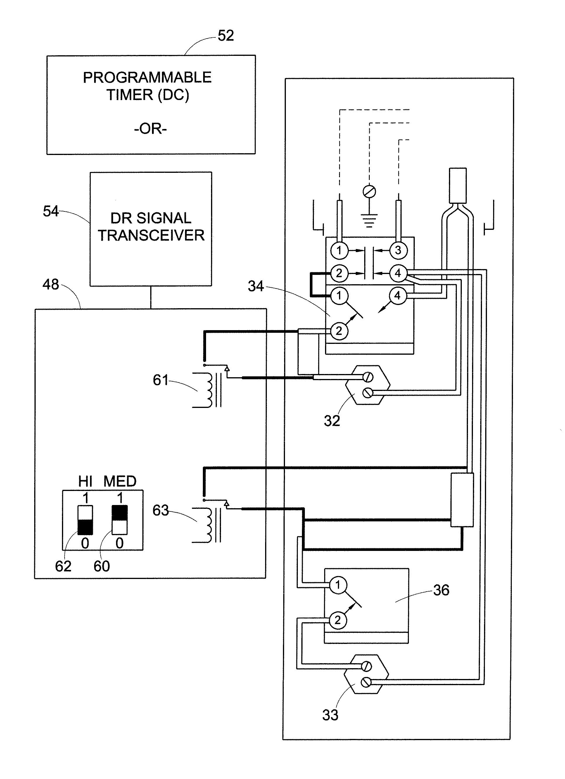
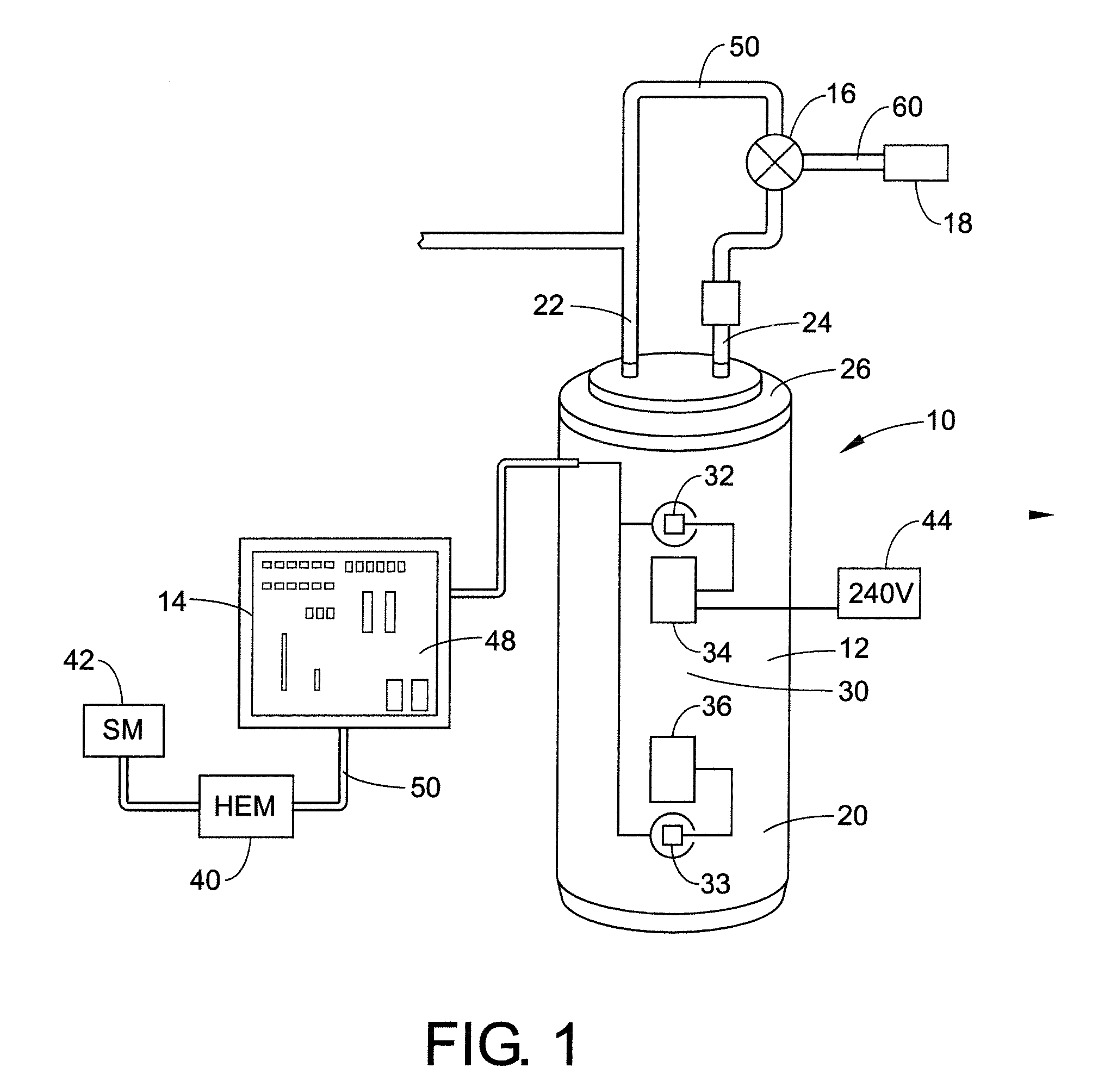
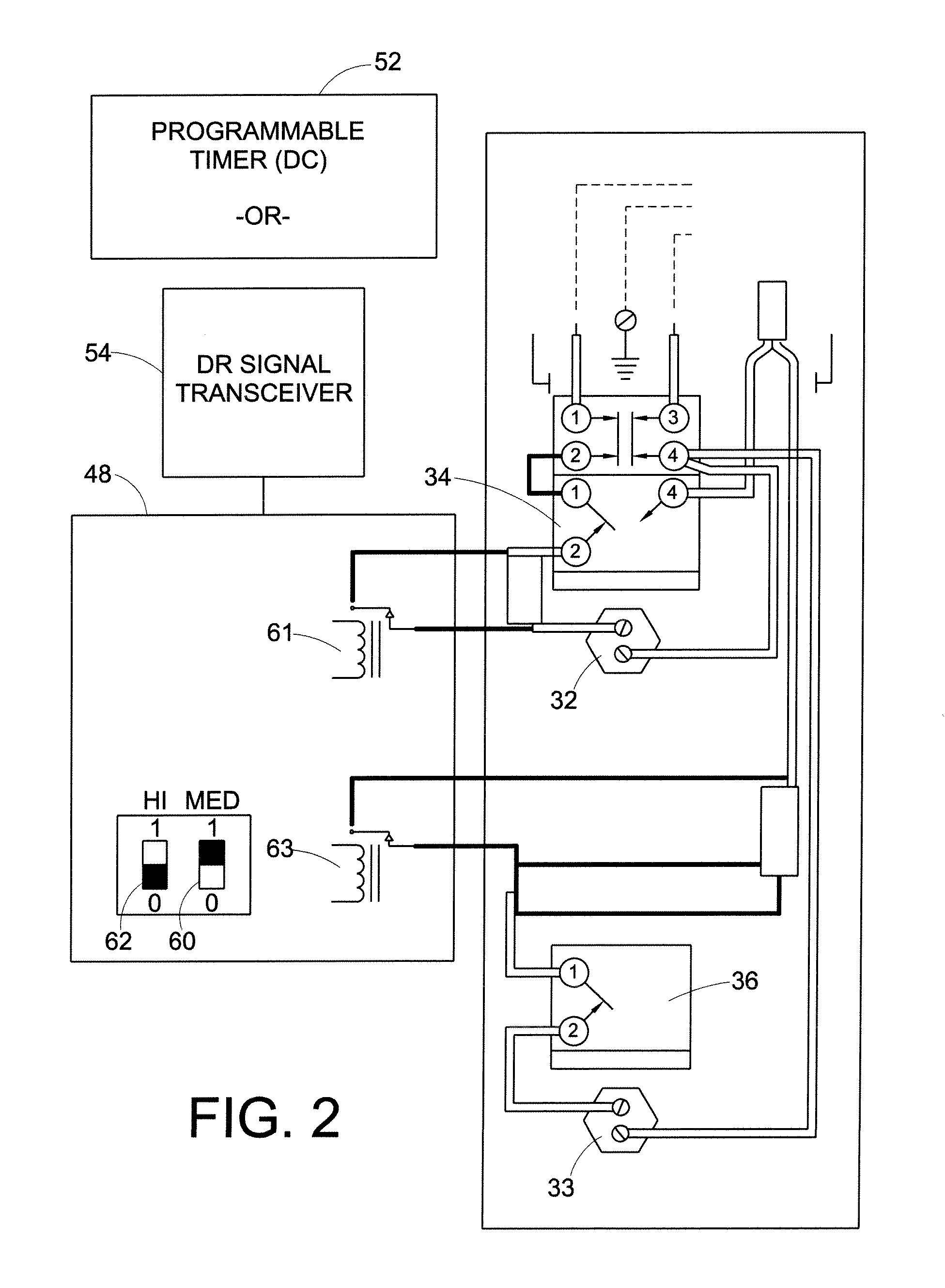
[0029]A water heating and storage system includes an insulated tank with upper and lower thermostatically controlled heating elements and an ope...


PUM


Abstract

A water heating control and storage system, including an insulated tank for containing water to be heated. The tank has at least two heating elements, including an upper heating element and a lower heating element. An operation control device receives a demand response signal and enables each element to independently heat water for usage. A method for controlling a water heating storage system includes providing an insulated tank for containing water to be heated; providing an upper heating element with a thermostat and thermal limiting device and a lower heating element with a thermostat and thermal limiting device to heat upper and lower portions of water inside the tank; and providing a pair of switches for enabling each of the heating elements to independently heat upper and lower portions of the water for usage.

Description

BACKGROUND OF THE DISCLOSURE[0001]The present disclosure relates generally to managing water heater systems. More particularly, it relates to managing and controlling water heater systems as a function of off-peak energy demand periods.[0002]Water heater storage tanks are used for storing and supplying hot water to households. A typical residential water heater holds about fifty gallons (190 liters) of water inside a steel reservoir tank. A thermostat is used to control the temperature of the water inside the tank. Many water heaters permit a consumer to set the thermostat to a temperature between 90 and 150 degrees Fahrenheit (F) (32 to 65 degrees Celsius (C)). To prevent scalding and to save energy, most consumers set the thermostat to heat the reservoir water to a temperature in a range between 120.0 degrees F. to 140.0 degrees F. (about forty-nine degrees C. to sixty degrees C.).[0003]A water heater typically delivers hot water according to the thermostat temperature setting. As...

Claims


Application Information

Patent Timeline
Patent Type & Authority Patents(United States)
IPC IPC(8): F24H1/20
CPCF24D17/0031F24D19/1051F24D19/1063F24H1/202F24H9/2021G05D23/1923F24D2240/26F28D20/0039F28F27/00F24H15/486F24H15/37F24H15/225F24H15/281F24H15/277F24H15/164
Inventor ROETKER, JOHN JOSEPHFINCH, MICHAEL
Owner HAIER US APPLIANCE SOLUTIONS INC
Learn More