
Power-supply control apparatus of vehicle

a power supply control and vehicle technology, applied in the direction of engine starters, dynamo-electric converter control, instruments, etc., can solve the problems of large-sized devices and increase manufacturing costs, and achieve the effect of simple constitution

Inactive Publication Date: 2013-07-30
MAZDA MOTOR CORP
View PDF15 Cites 6 Cited by
  • Summary
  • Abstract
  • Description
  • Claims
  • Application Information

AI Technical Summary

Benefits of technology

The present invention provides a power-supply control apparatus for vehicles that can properly supply electric power to the electric load in the vehicle with a simple constitution. This is achieved by preventing any improper situation in which the electric load does not receive sufficient electric power during the starting of the engine by the starter. This is particularly important because starting an engine with a low battery level can cause damage to the electric load. The power-supply control apparatus includes a coupling relay that stops the supply of power when the starter operates, an auto-stop controller that automatically stops the engine when a condition for automatic stopping is met, and a voltage detector that detects the voltage of the second electricity-storage device, which is a capacitor that has quicker charge-and-discharge performance than a lead-acid battery. In case of low battery level, the controller stops outputting the DC / DC convertor to prevent the lack of electric power for the electric load when restarting the engine. The electric power from the first electroity-storage device is prioritized to ensure sufficient power supply for the electric load. This prevents the first electric load from not working properly and avoids damage to the vehicle.

Problems solved by technology

Accordingly, there are demerits in that a large-capacity battery and a power-supply line including the set-up convertor which allows the large amount of electricity flowing through it may be required to be used despite providing the above-described set-up convertor and operation delay control means, which improperly causes a large-sized device and a manufacturing-cost increase.

Method used


Image

  • Power-supply control apparatus of vehicle
  • Power-supply control apparatus of vehicle
  • Power-supply control apparatus of vehicle

Examples


Embodiment Construction

[0023]Hereinafter, a preferable embodiment of the present invention will be described referring to the accompanying drawings.

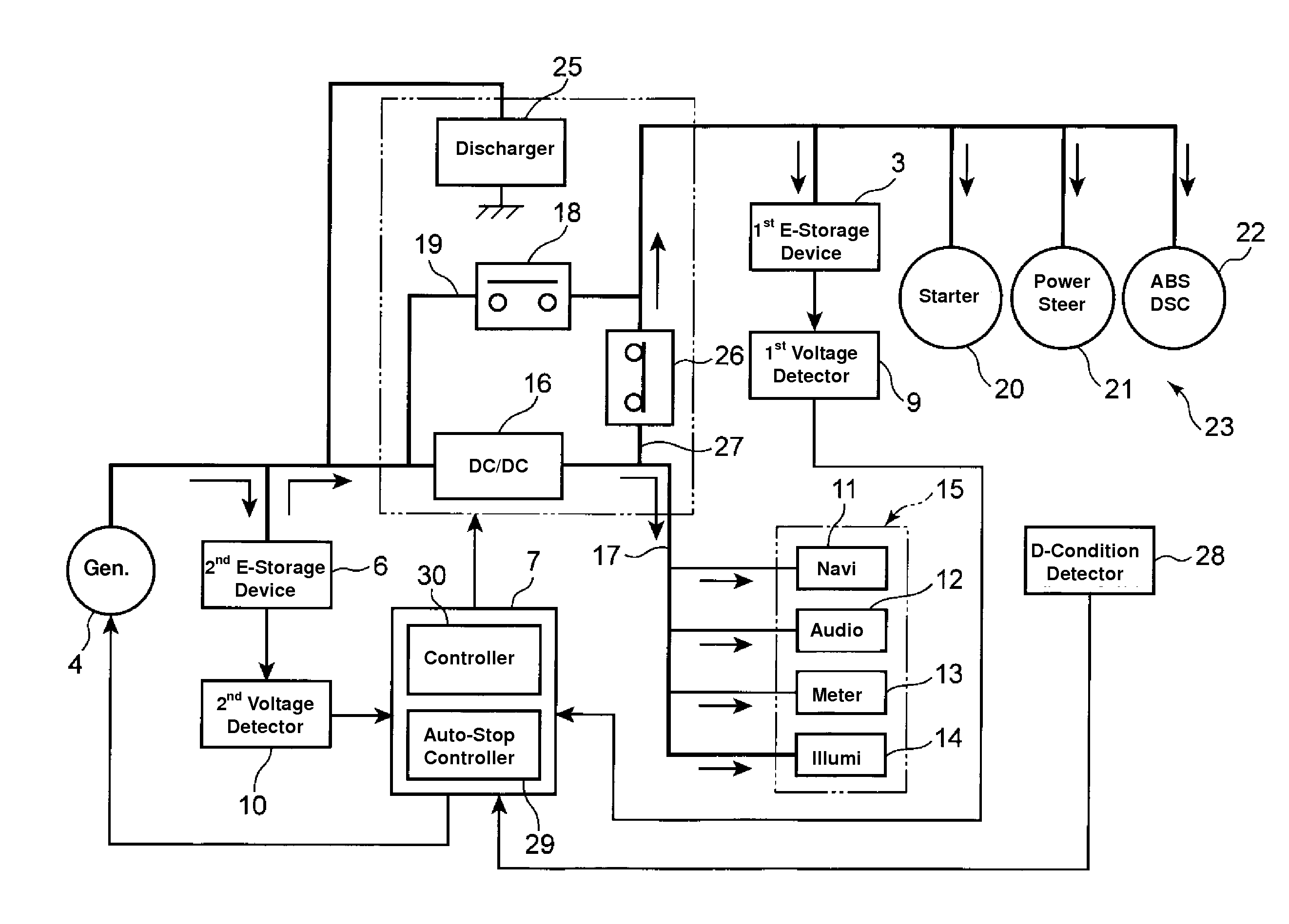
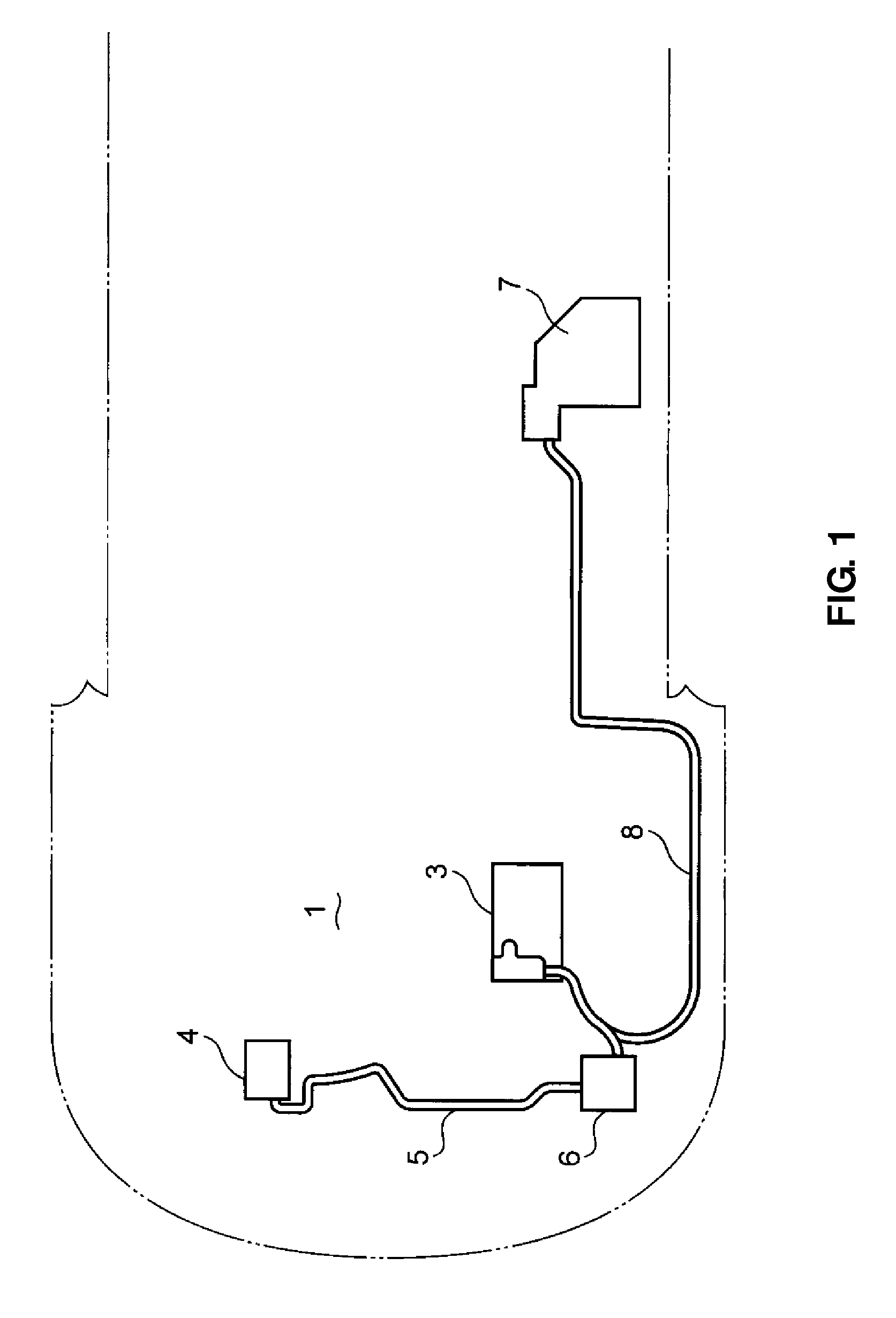
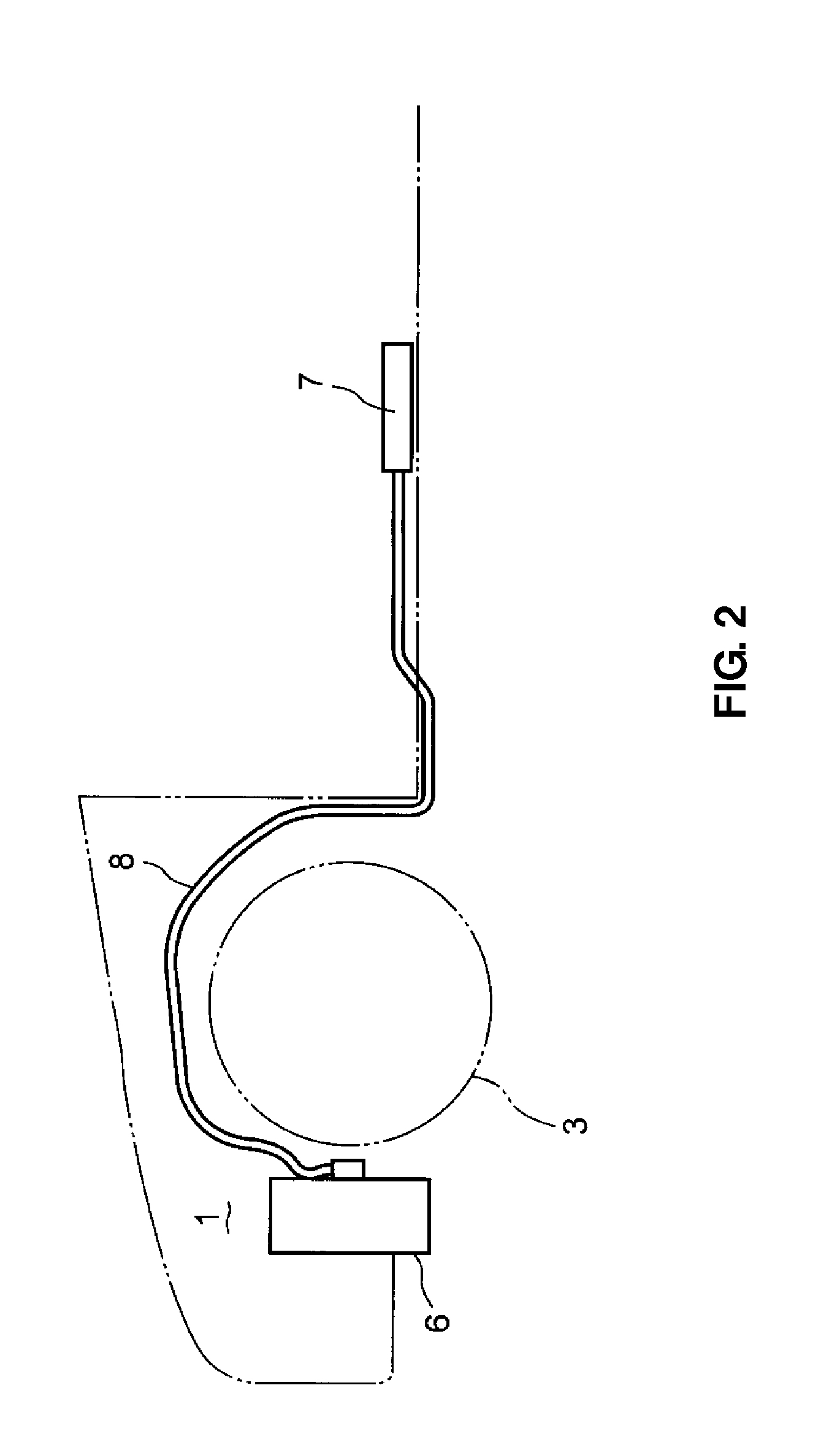
[0024]FIGS. 1 and 2 show a front structure of a vehicle equipped with a power-supply control apparatus according to the embodiment of the present invention. An engine (internal combustion engine) and a transmission, not illustrated, are disposed in an engine room 1 located at a front portion of the vehicle. On one side (a left side in the present embodiment) in the engine room 1 is disposed a first electricity-storage device 3 which is comprised of a lead-acid battery or the like which can store electric power for a long term. On the other side (a right side) in the engine room 1 is disposed a generator 4 which is comprised of an alternator which converts kinetic energy of the vehicle during a vehicle deceleration to electric energy for energy recovery.

[0025]A second electricity-storage device 6 which is coupled to the generator 4 via a first harness 5 is disp...


PUM


Abstract

A power-supply control apparatus of a vehicle comprises a first electricity-storage device to supply electric power to a starter for starting engine, a generator to convert kinetic energy of the vehicle during a vehicle deceleration to electric energy for energy recovery, a second electricity-storage device coupled to the generator to store the electric power from the generator thereat, a feeder circuit coupling the second electricity-storage device to an electric load with a relatively-small electric-load capacity via a DC / DC convertor, a coupling line coupling the second electricity-storage device to the first electricity-storage device via a coupling relay, and a controller to control the electric power passing through the feeder circuit and the coupling line, wherein the controller executes a control to make the coupling relay on the coupling line in an OFF state when the starter operates.

Description

BACKGROUND OF THE INVENTION[0001]The present invention relates to a harness arrangement structure of a vehicle which interconnects a battery device and an electric-power control device of a vehicle.[0002]The present invention relates to a power-supply control apparatus of a vehicle which comprises a first electricity-storage device to supply electric power to a starter for starting engine, a generator to convert kinetic energy of the vehicle during a vehicle deceleration to electric energy for energy recovery, and a second electricity-storage device coupled to the generator to store the electric power from the generator thereat.[0003]Conventionally, a power supply device for vehicle which reliably boosts battery power supply without being affected by a rise in ground potential caused by a rush current to an electric load, such as a head lamp as well as reliably supplies power to the electric load when restarting an engine from the time when the engine is stopped is known as disclose...

Claims


Application Information

Patent Timeline
Patent Type & Authority Patents(United States)
IPC IPC(8): H02P1/00B60L50/15
CPCH02J1/00H02J7/1438F02N11/0866F02N11/0818F02N2011/0888H02J2001/008H02J7/345H02J1/082H02J2310/46
Inventor KOTANI, KAZUYASANAI, HIDEKIYAMASHITA, TAKEHARUTAKAHASHI, MASAYOSHI
Owner MAZDA MOTOR CORP
Learn More