Hybrid fuel tank inerting system

a fuel tank and hybrid technology, applied in the direction of machines/engines, lighting and heating apparatus, separation processes, etc., can solve the problems ofinerting equipment and aircraft weight, and achieve the effect of reducing the concentration of oxidizable vapor

Active Publication Date: 2013-08-06
HONEYWELL INT INC
View PDF17 Cites 41 Cited by
  • Summary
  • Abstract
  • Description
  • Claims
  • Application Information

AI Technical Summary

Problems solved by technology

Inerting equipment also adds weight to an aircraft.

Method used


Image

  • Hybrid fuel tank inerting system
  • Hybrid fuel tank inerting system
  • Hybrid fuel tank inerting system

Examples


Embodiment Construction

[0012]The following detailed description is of the best currently contemplated modes of carrying out exemplary embodiments of the invention. The description is not to be taken in a limiting sense, but is made merely for the purpose of illustrating the general principles of the invention, since the scope of the invention is best defined by the appended claims.

[0013]Various inventive features are described below that can each be used independently of one another or in combination with other features.

[0014]Broadly, embodiments of the present invention generally provide an inerting system that employs fuel vapor condensation combined with fuel vapor oxidation to achieve a desired reduction in oxygen concentration level and fuel to air ratio.

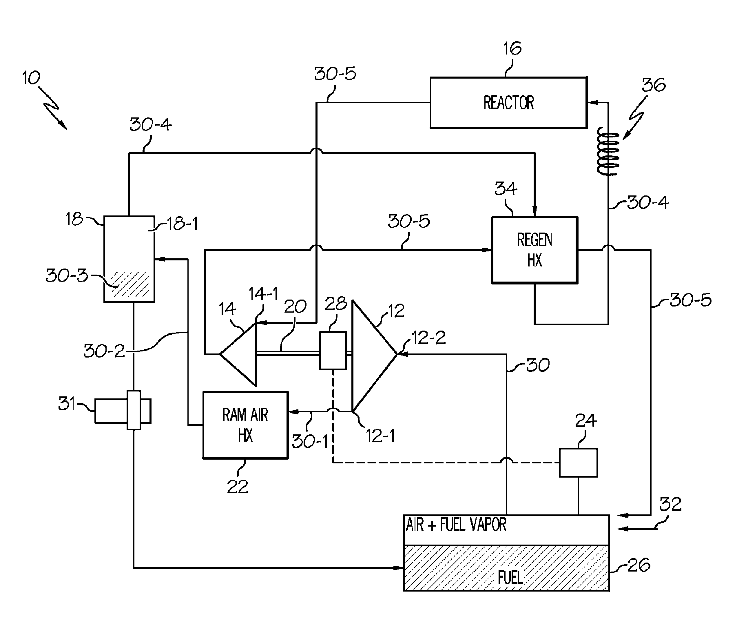
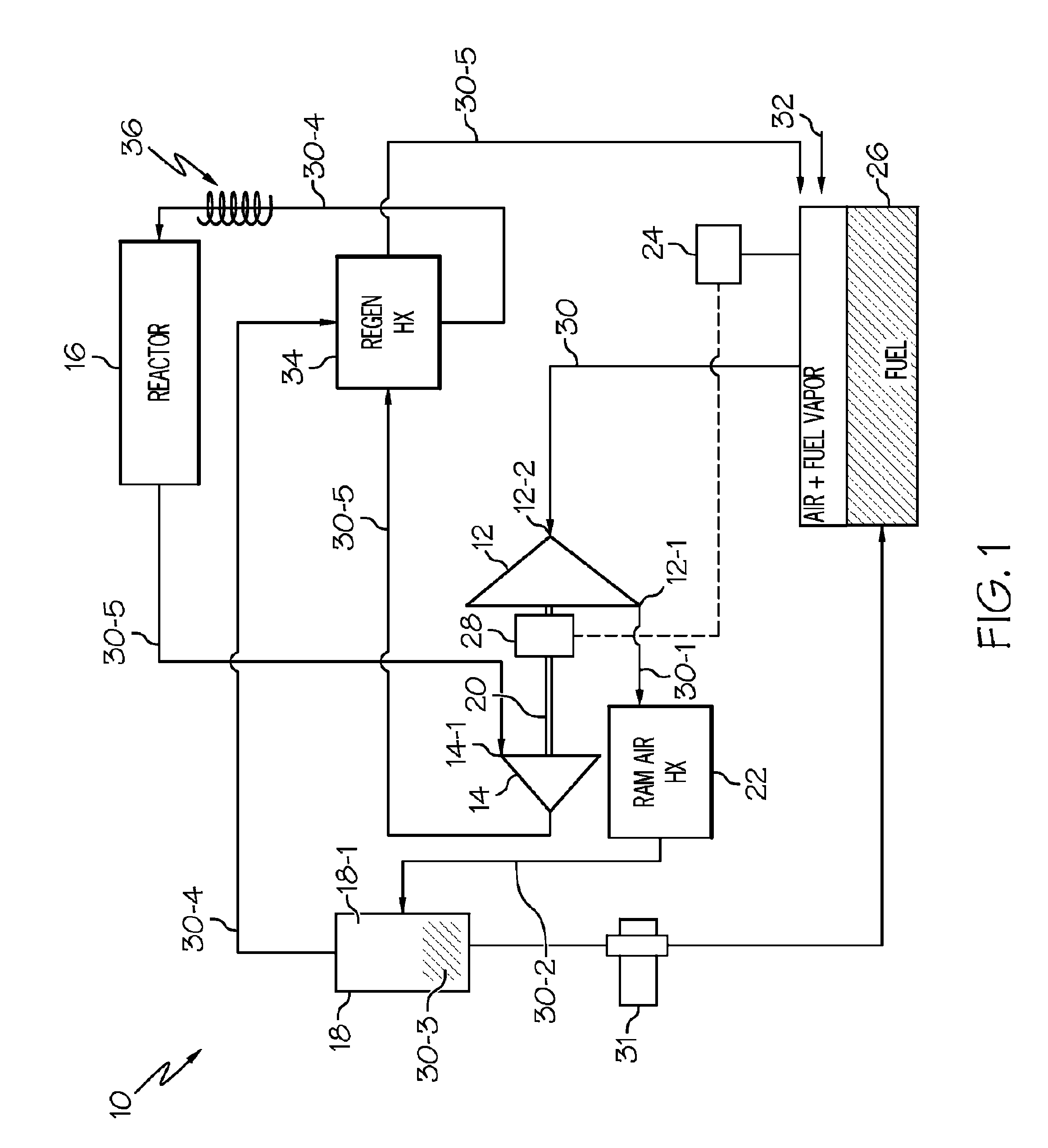
[0015]Referring now to FIG. 1, it may be seen that an exemplary embodiment of a fuel tank inerting system 10 may comprise a compressor 12, a turbine 14, an oxidation reactor 16 (e.g. a catalytic or thermal reactor) and a fuel coalescer 18. The compre...


PUM

PropertyMeasurementUnit
liquid outletaaaaaaaaaa
chemical compositionaaaaaaaaaa
concentrationaaaaaaaaaa

Abstract

A self-regulating system for reducing concentration of hydrocarbon vapor in a container may be performed by introducing air into the container and extracting a mixture of air and vapor from the container. The extracted mixture may be compressed with a compressor to produce a flow of compressed mixture of air and vapor. The compressed mixture may be passed through an oxidation reactor that may be either catalytic or thermal to produce a flow air and CO2. A turbine may be driven with the flow of air and CO2. The compressor may be driven with the turbine. Extraction from the container may continue until vapor concentration is low enough so that flow of CO2 and air from the reactor is insufficient to drive the turbine.

Description

BACKGROUND OF THE INVENTION[0001]The present invention generally relates to systems for maintaining aircraft fuel tank ullage in an inert state and more particularly to a hybrid fuel tank inerting system.[0002]Various inerting technologies have been employed to reduce explosion risk by altering the chemical composition of gas vapors in the fuel tanks. Inerting may be achieved by either reducing the oxygen concentration to <12% by volume and / or reducing the fuel to air ratio to <0.03 by weight. Such inerting techniques may include: in-flight purging of fuel vapor from tanks and condensing the purged vapor to reduce the fuel to air ratio; or in-flight generation of inert gas such as nitrogen or CO2 and injection of the inert gas into the fuels tanks to reduce oxygen concentration. Because all of these techniques are performed in-flight, the fuel supply of the aircraft must provide energy to operate the equipment that performs the inerting process. Inerting equipment also adds we...

Claims


Application Information

Patent Timeline
Patent Type & Authority Patents(United States)
IPC IPC(8): F02C7/00
CPCB01D53/75B64D37/32B01D53/002B01D53/72B01D2257/702B01D2259/4516B01D2259/4575
Inventor HAGH, BIJAN FZHENG, DAGUANGELSAYED, MAHMOUD ADELJOHNSON, RUSSELL W
Owner HONEYWELL INT INC
Why Eureka
Try Eureka