Clutch assembly with formed retention ring

a technology of retention ring and clutch housing, which is applied in the field of clutches, can solve the problems of the release of the snap ring from the clutch housing, and achieve the effects of reducing the thickness of the clutch housing, facilitating the deformation of the open end, and reducing the mass of the typical housing

Inactive Publication Date: 2013-08-06
SZUBA CONSULTING +1
View PDF26 Cites 4 Cited by
  • Summary
  • Abstract
  • Description
  • Claims
  • Application Information

AI Technical Summary

Benefits of technology

[0006]The inventive clutch and clutch housing eliminates the lance-and-form snap ring groove known to prior art clutch housings, which typically causes failure in an automotive transmission. The retainer of the present clutch housing is defined by deforming an annular wall of the housing radially inwardly to define the retainer between the upper end of the splines and the deform wall. In effect, the snap ring retention is achieved by “hemming” the top of the housing and results in a full 360° retention. This configuration of the snap ring retainer eliminates the weaknesses associated with the prior art lance-and-formed snap ring groove that are caused from forming a reverse lance cut in the plurality of splines formed in the clutch housing. This lance cut causes a stress rising condition resulting a release of the snap ring from the clutch housing. It is believed that the thickness of the clutch housing can now be reduced by upwards of 0.5 millimeters providing a 20% decrease in the mass of a typical housing. Furthermore, the splines no longer extend to the open end of the clutch housing, but are spaced from the open end of the housing to facilitate the deformation of the open end to form the retainer from the snap ring. This facilitates a reduction of the axial length of the clutch housing reducing the packaging space required of each clutch of the automotive transmission.

Problems solved by technology

This lance cut causes a stress rising condition resulting a release of the snap ring from the clutch housing.

Method used


Image

  • Clutch assembly with formed retention ring
  • Clutch assembly with formed retention ring
  • Clutch assembly with formed retention ring

Examples


Embodiment Construction

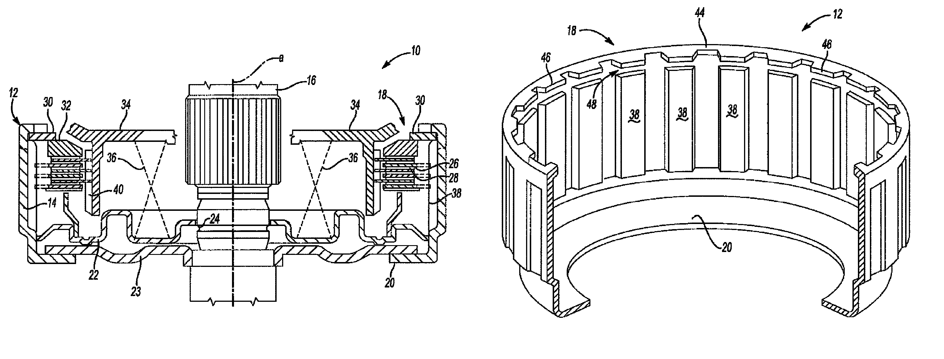
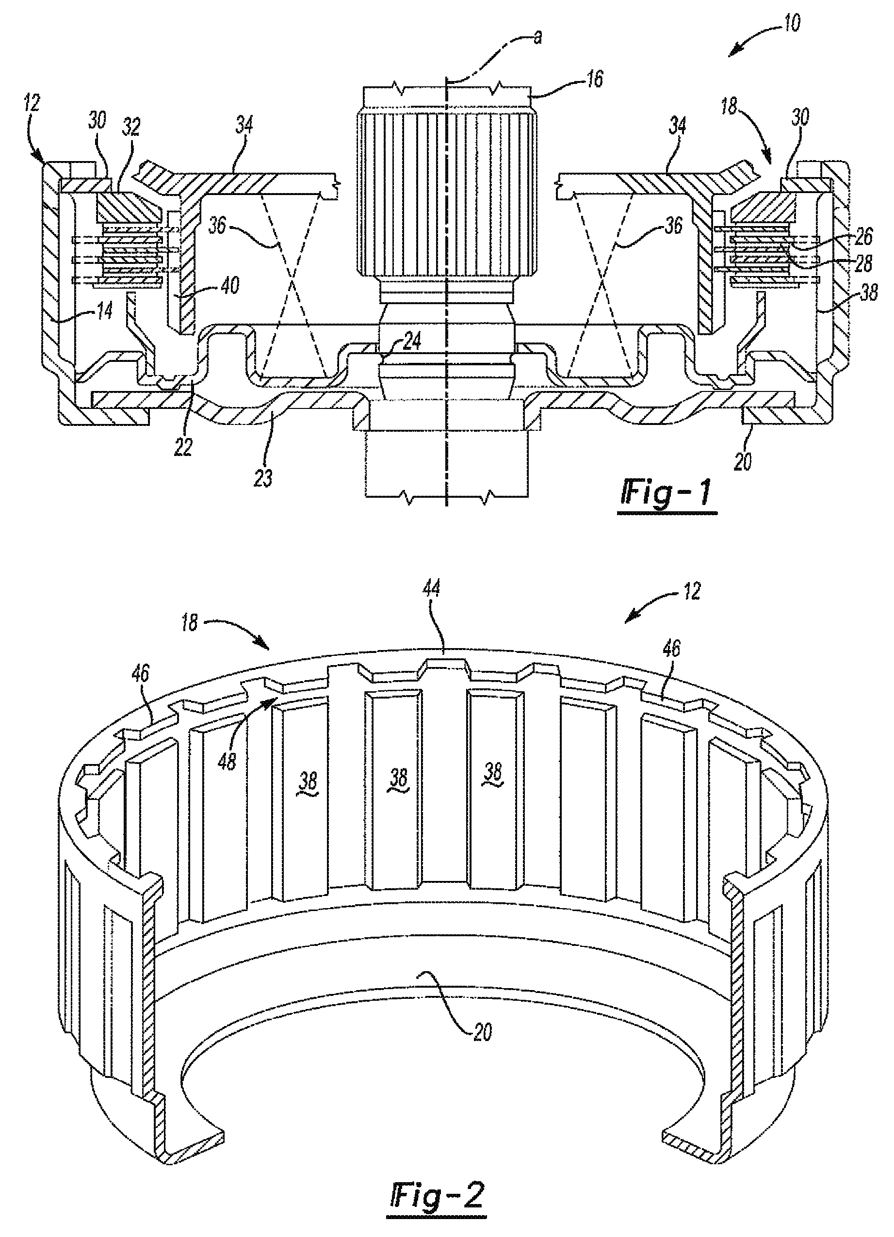
[0022]Referring to FIG. 1, a side sectional view of the clutch assembly of the present invention is generally shown at 10. The assembly 10 includes a housing 12 defined by an annular wall 14. The annular wall 14 circumscribes a transmission shaft 16 that defines a shaft axis A. The annular wall 14 of the housing 12 extends axially between an open end 18 and a floor 20. The floor 20 extends radially inwardly toward the transmission shaft 16. A piston 22 circumscribes the transmission shaft 16 and is positioned adjacent the floor 20 of the housing 12. A seal 23 seals the floor 20 of the housing 12 to the transmission shaft 16. Transmission fluid pumps through the transmission shaft 16 through outlets 24 and to the space located between the piston 22 and the floor 20 of the housing 12 to shift the clutch assembly 10 in a known manner. A fibrous plate 28 circumscribes the transmission shaft 16 and is positioned in an abutting relationship between the piston 22 and a plurality of clutch ...


PUM

PropertyMeasurementUnit
thicknessaaaaaaaaaa
diameteraaaaaaaaaa
thicknessaaaaaaaaaa

Abstract

A clutch assembly for a vehicle transmission includes a housing defined by a wall having an annular configuration circumscribing a clutch axis. The wall extends between an open end and a floor. The floor extends inwardly from the wall toward the clutch axis. A plurality of splines formed in the wall and each is spaced from the open end of the housing. A snap ring retains clutch plates in the housing. The open end of the wall is deformed inwardly toward the clutch axis defining a retainer for retaining the snap ring within the housing.

Description

BACKGROUND OF THE INVENTION[0001]This application is a continuation of U.S. patent application Ser. No. 13 / 153,869 filed on Jun. 6, 2011 which is a U.S. non-provisional application which claims priority to U.S. Provisional Patent Application Ser. No. 61 / 351,311, filed Jun. 4, 2010 and incorporated herein by reference in its entirety. The present invention relates generally toward a clutch for use in an automotive transmission. More specifically, the present invention relates toward an improved clutch housing and retention assembly.[0002]Clutches are known to be used in an automatic transmission assembled to a power train of a vehicle. An increased number of clutches assembled into a transmission are also known to improve mileage performance of a vehicle. For example, a transmission having only four clutches does not perform as well, or provide as good mileage performance, as a transmission having six, or even eight clutches. Due to the increasing cost of fuel, most vehicle companies...

Claims


Application Information

Patent Timeline
Patent Type & Authority Patents(United States)
IPC IPC(8): B21D5/00B21D15/02B21D39/00B21D53/88
CPCF16D13/646F16D13/52F16D13/683Y10T29/49826Y10T29/49622Y10T29/49938F16D13/70F16D25/0638
Inventor SZUBA, JOSEPH
Owner SZUBA CONSULTING
Why Eureka
Try Eureka