Hydraulic control device

a hydraulic control device and control device technology, applied in the direction of water mains, machine/engines, service pipe systems, etc., can solve the problems of increased assembling man-hours, increased parts and assembly costs, and damage to bolted parts, so as to prevent the flow of hydraulic oil and reduce the height of the magnet

Inactive Publication Date: 2013-08-06
AISIN AW CO LTD
View PDF11 Cites 5 Cited by
  • Summary
  • Abstract
  • Description
  • Claims
  • Application Information

AI Technical Summary

Benefits of technology

[0007]The hydraulic control device of the invention has a main object of stably and easily fixing a strainer between a valve body and an oil pan while curbing a complication in structure and an increase in the number of parts.
[0010]With the hydraulic control device of the invention, the strainer for filtering the hydraulic oil from the oil pan is fixed to the oil pan by the magnetic force of at least one magnet. Because of this, it is possible to stably and easily fix the strainer between the valve body and the oil pan while curbing a complication in structure and an increase in the number of parts in a case of using a fastener such as a bolt. Also, with the hydraulic control device of the invention, it is also possible to capture foreign particles such as metal powder contained in the hydraulic oil in the oil pan using the magnet for fixing the strainer to the oil pan. The magnet may be adsorbed to both the oil pan and an oil pan side portion of the strainer, and may be fixed (bonded) to one of the two and adsorbed to the other.
[0012]By disposing the magnet between the projection provided on the bottom portion of the housing of the strainer and the oil pan in this way, it is possible to reduce the height of the magnet, and also, to appropriately set the distance between the oil pan and strainer. Also, when the magnetic force of the magnet disposed between the projection of the housing and the oil pan acts on the back side of the projection, that is, the side of the depression in the housing, it is possible to attract foreign particles such as metal powder contained in the hydraulic oil in the housing of the strainer with the magnetic force of the magnet, and retain them in the depression.
[0013]Furthermore, at least the projection of the housing may be formed from a magnetic body. Because of this, by causing the magnetic force of the magnet disposed between the projection of the housing and the oil pan to act more strongly on the back side of the projection, that is, the side of the depression in the housing, it is possible to more strongly attract foreign particles such as metal powder contained in the hydraulic oil in the housing of the strainer with the magnetic force of the magnet, and more reliably retain them in the depression.
[0014]Furthermore, the magnet may be not disposed on a straight line connecting a hydraulic oil inflow portion connecting with the oil pan and a hydraulic oil inlet of the strainer. In this way, it is possible to prevent the flow of the hydraulic oil in the oil pan from being impeded by the magnet.

Problems solved by technology

It is not preferable to fix the strainer device to the valve body using a bolt, as in the heretofore described hydraulic control device described in JP-A-58-94671, because it involves an increase in the number of parts and an increase in assembling man-hours.
Also, (there is also a danger of a bolted portion being damaged in a case of using a strainer device made of a resin.
Furthermore,) even in the event that the fixing claws or the like are provided on the strainer device, and the strainer device is fixed to the valve body or the like without using a bolt, as in the hydraulic control device described in JP-A-2000-249214, there is a danger of the structure of the hydraulic control device being complicated, eventually involving an increase in the number of parts and an increase in man-hours.

Method used


Image

  • Hydraulic control device
  • Hydraulic control device
  • Hydraulic control device

Examples


Embodiment Construction

[0018]Next, a description will be given, using an embodiment, of a mode for carrying out the invention.

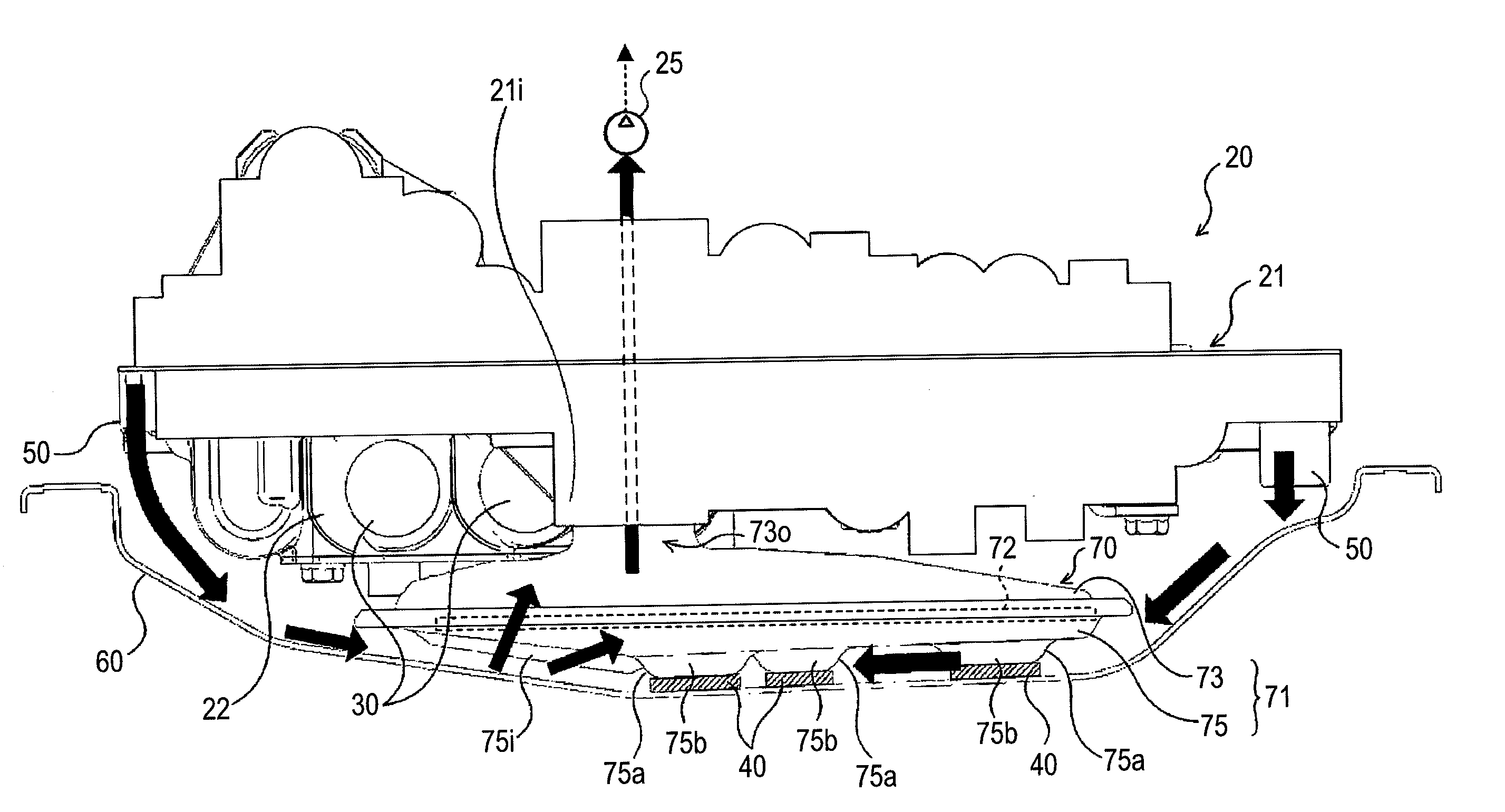
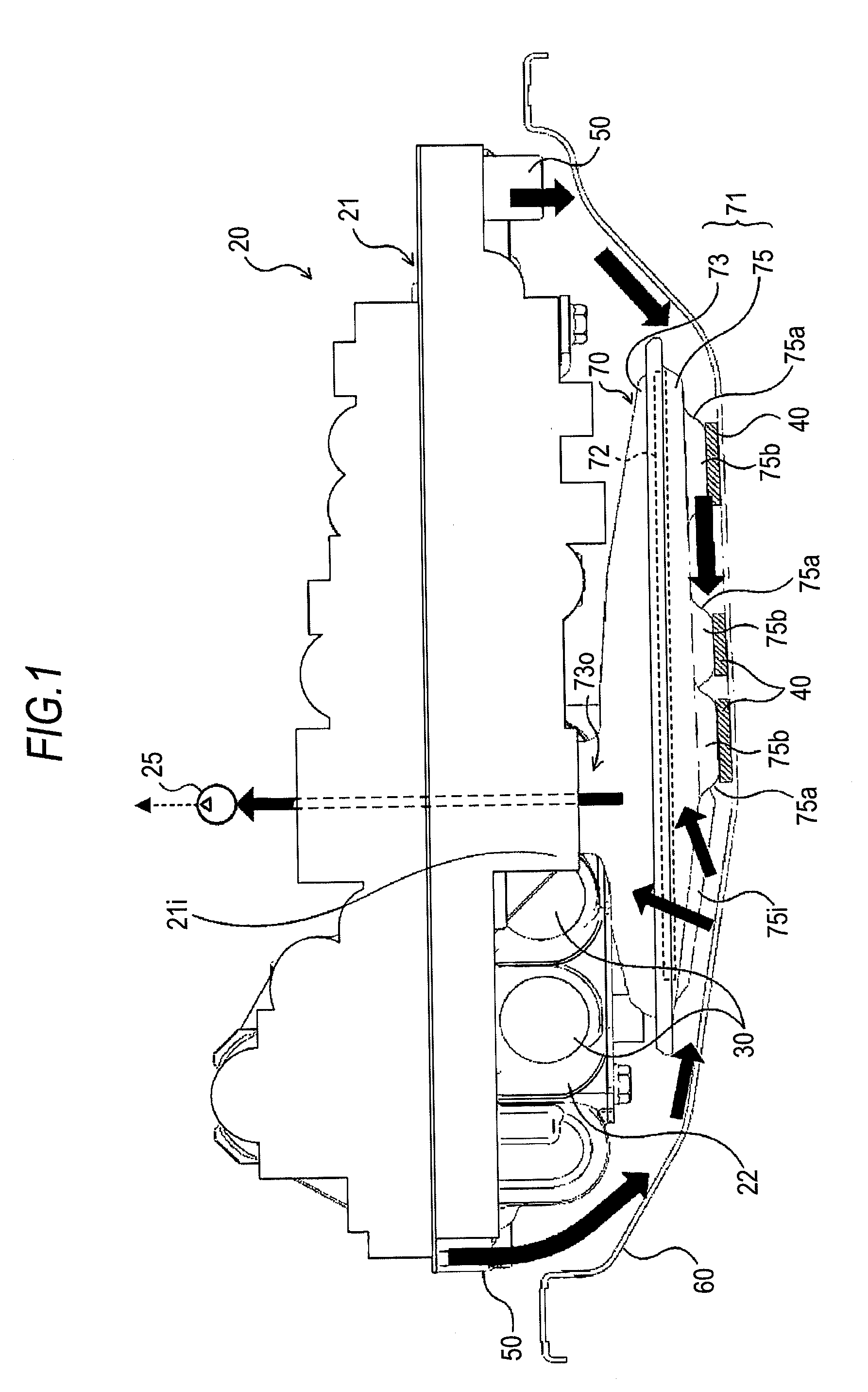
[0019]FIG. 1 is an illustration showing a hydraulic control device 20 according to the embodiment of the invention. The hydraulic control device 20 of the embodiment configures, for example, a power transmission device together with an automatic transmission, a differential gear, and the like, which transmit power from an unshown engine mounted in an automobile to a drive shaft (a propeller shaft), and is used for a speed change control or the like of the automatic transmission. The hydraulic control device 20 of the embodiment includes a valve body 21 having an unshown plurality of oil passages, a plurality of solenoid valves 30 which, being incorporated in the valve body 21, configure a hydraulic circuit together with the oil passages of the valve body 21, an unshown control module for controlling the whole of the automatic transmission, an oil pan 60 which, as well as being form...


PUM

PropertyMeasurementUnit
magnetic forceaaaaaaaaaa
heightaaaaaaaaaa
pressureaaaaaaaaaa

Abstract

A hydraulic control device includes a valve body having oil passages, a solenoid valve incorporated in the valve body, an oil pan that is disposed below the valve body and that accumulates hydraulic oil, and a strainer which, as well as being disposed between the valve body and the oil pan, has a filtering medium which filters the hydraulic oil suctioned from the oil pan. The strainer is fixed to the oil pan by a magnetic force of at least one magnet.

Description

INCORPORATION BY REFERENCE[0001]The disclosure of Japanese Patent Application No. 2010-079394 filed on Mar. 30, 2010, including the specification, drawings and abstract thereof, is incorporated herein by reference in its entirety.BACKGROUND OF THE INVENTION[0002]1. Field of the Invention[0003]The present invention relates to a hydraulic control device including a valve body having a plurality of oil passages, an oil pan which, being disposed below the valve body, accumulates hydraulic oil, and a strainer which, as well as being disposed between the valve body and the oil pan, has a filtering medium which filters the hydraulic oil suctioned from the oil pan.[0004]2. Description of the Related Art[0005]Heretofore, as this kind of hydraulic control device, one including a valve body assembled with a control valve, an oil pan which stores oil to be provided to the valve body, and a strainer device which, as well as being disposed inside the oil pan, has a filter which filters the oil su...

Claims


Application Information

Patent Timeline
Patent Type & Authority Patents(United States)
IPC IPC(8): F01M11/03B01D29/00B01D35/06F16H57/04
CPCF16H57/0404F16H57/0452Y10T137/794
Inventor TSUNEMATSU, KOISHIKAWA, TOMOYUKIYAMANAKA, ATSUSHI
Owner AISIN AW CO LTD
Why Eureka
Try Eureka