
Method for determining an item of travel direction information for a vehicle, and sensor device for a vehicle

a technology for vehicle travel direction and sensor device, which is applied in the direction of instruments, navigation instruments, structural/machine measurement, etc., can solve the problems of changing track displacement, and significant steering wheel angle conversion, and achieve stable and reliable signal, low error rate, and high speed

Inactive Publication Date: 2013-08-06
ROBERT BOSCH GMBH
View PDF12 Cites 0 Cited by
  • Summary
  • Abstract
  • Description
  • Claims
  • Application Information

AI Technical Summary

Benefits of technology

[0009]At a comparatively high speed it is considered advantageous to use the determined yaw rate of the vehicle in order to determine an item of travel direction information. Here, a comparatively high speed is to be understood as for example a speed of 30 kph or greater. At such high speeds, the yaw rate supplies a stable and reliable signal with the aid of which the item of travel direction information, for example a wheel deflection angle, can be determined very precisely and with a low error rate. However, due to the intrinsic noise of the yaw rate signal at low vehicle speeds, it is more advantageous not to use the yaw rate to determine the item of travel direction information, but rather instead to determine the item of travel direction information via an evaluation of the specific wheel paths of the rear wheels and / or of the front wheels. This is advantageous because the specific wheel paths of the rear wheels and of the front wheels can be easily and reliably determined at a comparatively low speed of the vehicle, for example a speed below 30 kph.
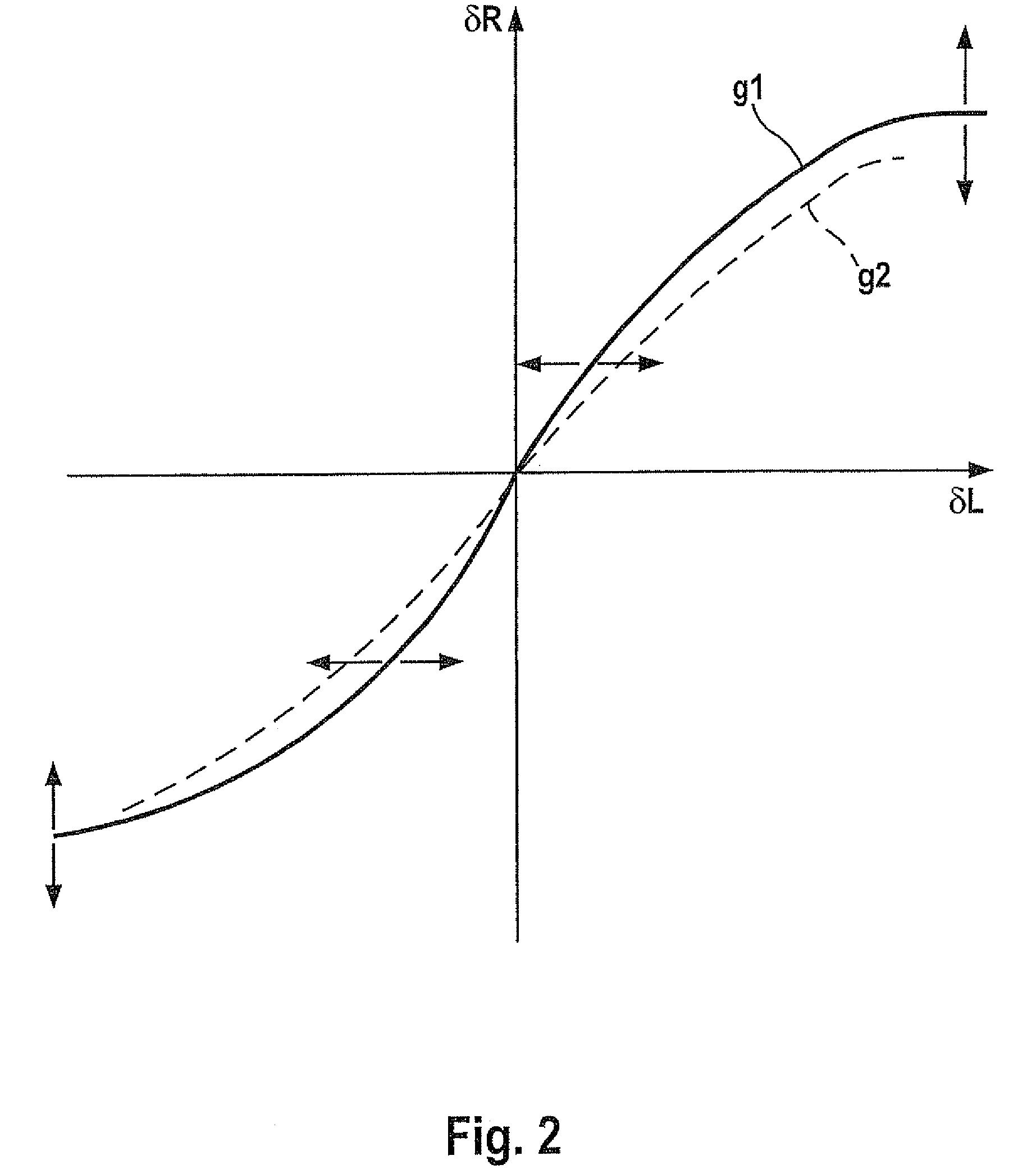
[0013]Example embodiments of the present invention provide a method for determining a conversion relation relating to a conversion of a travel direction specification into a direction of travel of a vehicle, including: determination of at least one item of travel direction information relating to at least one travel direction specification according to one of the methods in the foregoing paragraphs, and determination of the conversion relation relating to the conversion of a travel direction specification into a direction of travel on the basis of the at least one travel direction specification and the at least one item of travel direction information. Example embodiments of the present invention thus offer, for example, the possibility of recognizing deviations that occur as the vehicle ages in the conversion of a travel direction specification into a travel direction, and correspondingly adapting the conversion relation.
[0015]Example embodiments of the present invention also provide a method for operating an automatic travel direction specification system of a vehicle, including: outputting of at least one travel direction specification by the automatic travel direction specification system; determination of a conversion relation regarding a conversion of a travel direction specification into a direction of travel of the vehicle according to the methods in the foregoing paragraphs; and determination of a corrected travel direction specification for at least one additional travel direction specification of the automatic travel direction specification system, using the conversion relation. Thus, the travel direction specifications of the automatic travel direction specification system can be adapted to the current state of the vehicle components for the conversion of a travel direction specification into a direction of travel. This ensures uniform quality of the functioning of the automatic travel direction specification system for the entire lifetime of the system.

Problems solved by technology

However, the steering wheel angle conversion may change significantly during operation of the vehicle.
Even slight contact of a wheel of the vehicle with a curb may for example result in track displacement and thus in a changed steering wheel angle conversion.
Potholes in a street may also permanently change the mechanics of the steering wheel angle conversion.
Thus, during use of a vehicle there is a high probability that changes will occur in the steering wheel angle conversion.
In particular, larger deviations between a steering wheel angle conversion before operation of the vehicle and a current steering wheel angle conversion present a potential source of errors during operation of the parking system.
However, at low vehicle speeds the yaw rate of a vehicle can be determined only imprecisely.
Therefore, the system and the method described in U.S. Patent Application Publication No. 2007 / 0213901 are poorly suited for parking a vehicle in a parking space.
Even small errors in the steering wheel angle can cause, after driving by a potential parking space, a false orientation or positional calculation of the vehicle, which can result either in enormous deviations during the parking process or in unjustified rejection of the parking space.

Method used


Image

  • Method for determining an item of travel direction information for a vehicle, and sensor device for a vehicle
  • Method for determining an item of travel direction information for a vehicle, and sensor device for a vehicle
  • Method for determining an item of travel direction information for a vehicle, and sensor device for a vehicle

Examples


Embodiment Construction

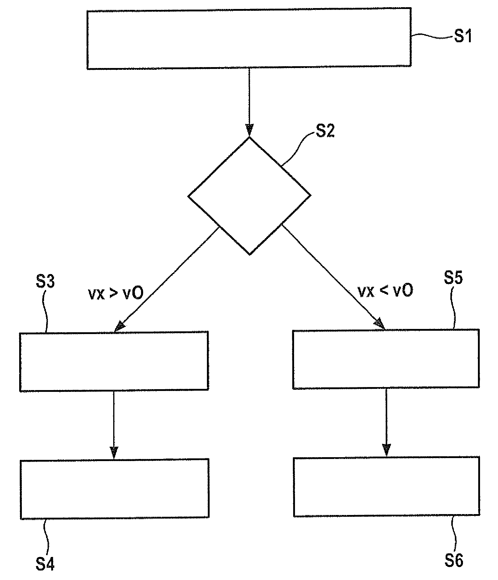
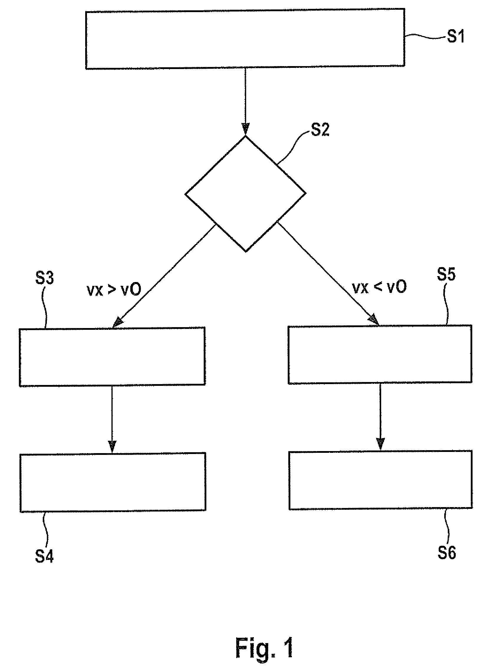
[0023]FIG. 1 shows a flow diagram representing an example embodiment of the method for determining an item of travel direction information for a vehicle.

[0024]In a first method step S1, a current speed vx of the moving vehicle is determined. Speed vx is preferably the longitudinal speed of the vehicle. Subsequently, in a method step S2 speed vx is compared with at least one specified comparison speed v0. In the method illustrated in FIG. 1, determined speed vx is compared only with comparison speed v0. In a further development, described below, of the method of FIG. 1, speed vx of the moving vehicle is compared with a first comparison speed and with a second comparison speed.

[0025]If speed vx of the vehicle is greater than the at least one specified comparison speed v0, then in a method step S3 a current yaw rate ψ of the vehicle is determined. For the definition of the yaw rate ψ, see Equation 1:

[0026]ψ=vx·δR(a+c)·(1+vx2vCH2)(Eq⁢⁢1)

where vCH is a characteristic speed, δR is a wheel...


PUM


Abstract

A method for determining an item of travel information for a vehicle includes: determination of a speed of the vehicle; comparison of the speed with at least one specified comparison speed; if the speed is greater than the at least one specified comparison speed, determination of a yaw rate of the vehicle and determination of the item of travel direction information on the basis of the determined yaw rate; and, if the speed is less than the at least one specified comparison speed, determination of a first wheel path of a first wheel of an axle of the vehicle and a second wheel path of a second wheel of the axle, and determination of the item of travel direction information on the basis of the first wheel path and the second wheel path.

Description

CROSS-REFERENCE TO RELATED APPLICATIONS[0001]The present application claims priority to Application No. 10 2008 054 648.8, filed in the Federal Republic of Germany on Dec. 15, 2008, which is expressly incorporated herein in its entirety by reference thereto.FIELD OF THE INVENTION[0002]The present invention relates to a method for determining an item of travel direction information for a vehicle. In addition, the present invention relates to a corresponding sensor device for a vehicle.BACKGROUND INFORMATION[0003]A vehicle is often equipped with an automatic travel direction specification system, such as an automatic parking system. A travel direction specification system (driver assistance system) fashioned as a parking system is for example designed to give steering instructions to the driver during the process of parking a vehicle in a parking space. The parking system may also be designed for an automatic steering wheel controlling, so that the driver does not himself have to oper...

Claims


Application Information

Patent Timeline
Patent Type & Authority Patents(United States)
IPC IPC(8): G01C17/38B60W40/10
CPCB60W40/10
Inventor NIEMZ, VOLKER
Owner ROBERT BOSCH GMBH
Learn More