
Exhaust gas retreatment system of an internal combustion engine and method for operating the same

a technology of exhaust gas retreatment and internal combustion engine, which is applied in the direction of exhaust treatment, structural/machine measurement, instruments, etc., can solve the problems of increasing the carbon component or soot component in the particle filter, the clogging of the particle filter, and the limited amount of nitrogen dioxide that can be achieved, so as to achieve the effect of reliable derivation of soot burn-off and easy and reliable determination

Active Publication Date: 2017-06-13
DORING ANDREAS
View PDF15 Cites 5 Cited by
  • Summary
  • Abstract
  • Description
  • Claims
  • Application Information

AI Technical Summary

Benefits of technology

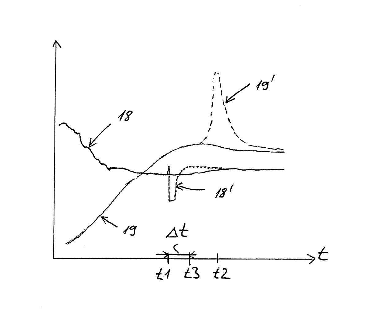
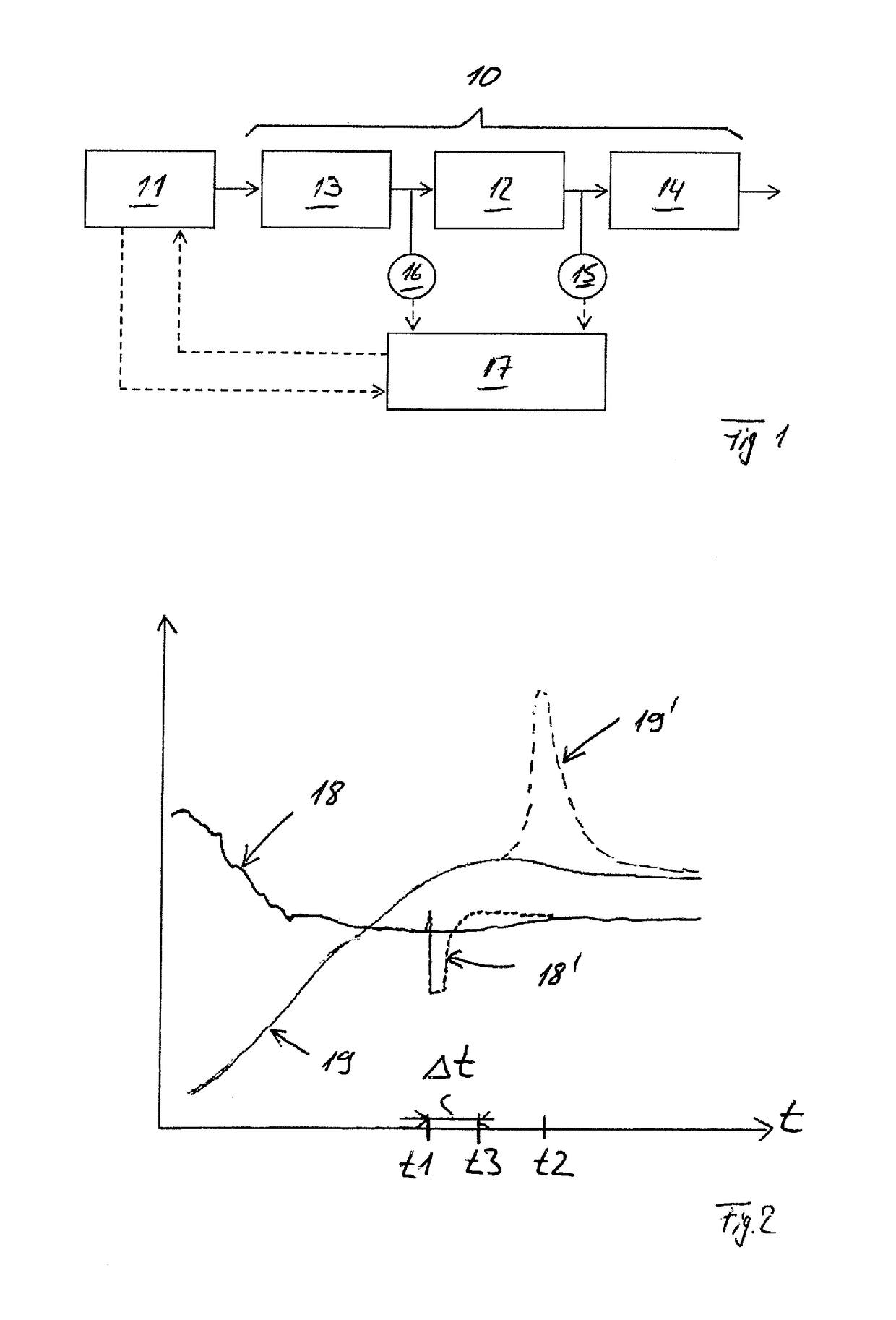
[0019]With the invention it is proposed for the first time to position a sensor downstream of a particle filter, which serves to measure the oxygen content and / or the NOx content in the exhaust gas. With the help of such a sensor it is possible, with active regeneration and with passive regeneration of a particle filter, to reliably deduce the soot burn-off that is occurring within a short time. Furthermore, based on the measurement signal provided by this sensor, i.e., based on the oxygen content or NOx content in the exhaust gas downstream of the particle filter determined by the first sensor, the charge condition of the particle filter with soot before the soot burn-off and / or the temperature increase of the particle filter as a consequence of the soot burn-off and / or the speed of the soot burn-off can be easily and reliably determined.

Problems solved by technology

As a result the achievable component of nitrogen dioxide is greatly limited at high temperatures.
In particular when, with such a passive regeneration of the particle filter, no complete conversion of the carbonaceous fine material particles or of the soot deposited in the particle filter can take place, the carbon component or soot component in the particle filter increases, wherein the particle filter then has a tendency towards clogging, as a result of which ultimately the exhaust gas backpressure at an internal combustion engine situated upstream of the exhaust gas retreatment system increases.
A rising exhaust gas backpressure at the internal combustion engine reduces the power of the internal combustion engine and causes increased fuel consumption.
The use of such particle filters with catalytic coating, however, can only insufficiently prevent the charging of the particle filter with carbonaceous fine material particles, i.e., with soot, at low exhaust gas temperatures.
If the soot charge of the particle filter exceeds a certain limit, which depending on the filter material is between 3 and 10 g of soot / l of filter substrate, uncontrolled ignition of the soot can occur.
In this case, the soot combusts suddenly, which because of the exothermic of the carbon oxidation results in a temperature increase of above 1000° C., which results in a thermal damaging of the filter material.
In the case of an active regeneration of a particle filter by burning of the soot particles there is likewise the risk that soot charges of the particle filter are high enough that due to the exothermic carbon oxidation in the particle filter, a severe temperature increase of above 1000° C. develops.
In the case of such a severe temperature increase damage to the particle filter and / or exhaust gas retreatment assemblies connected downstream can occur.
As already explained, this is also problematic in the case of a passive regeneration of a particle.
Here, too, a temperature increase of over 1000° C. in the particle filter can occur as a result of a severe exothermic reaction, as a result of which the particle filter and / or exhaust gas retreatment assemblies connected downstream of the same in turn are exposed to a damage hazard.
To date it is not possible, in particular when with a passive regeneration of a particle filter an uncontrolled burning-off of fine material particles or soot particles occurs in the particle filter, to detect this in time.
Furthermore, it is not possible to date in particular when fine material particles or soot particles in terms of active regeneration burn off in a controlled or alternatively uncontrolled manner, to safely and reliably determine the degree of charging of the particle filter with soot prior to the soot burn-off and / or the temperature increase of the particle filter as a consequence of the soot burn-off and / or a speed of the soot burn-off.

Method used


Image

  • Exhaust gas retreatment system of an internal combustion engine and method for operating the same
  • Exhaust gas retreatment system of an internal combustion engine and method for operating the same

Examples


Embodiment Construction

[0028]FIG. 1 shows a schematic representation of an exhaust gas retreatment system 10 of an internal combustion engine 11, wherein according to FIG. 1 the exhaust gas retreatment system 10 comprises a particle filter 12. The exhaust gas retreatment system 10 further comprises at least one exhaust gas retreatment assembly 13 positioned, in the flow direction of the exhaust gas, upstream of the particle filter 12 and at least one exhaust gas retreatment assembly 14 positioned, in the flow direction of the exhaust gas, downstream of the particle filter 12.

[0029]An exhaust gas retreatment assembly 13 positioned, in the flow direction of the exhaust gas, upstream of the particle filter 12 is preferentially an oxidation catalytic converter.

[0030]An exhaust gas retreatment assembly 14 positioned, in the flow direction of the exhaust gas, downstream of the particle filter 12 preferentially is an SCR-catalytic converter and / or a silencer and / or a desulpherisation assembly and / or a heat excha...


PUM


Abstract

An exhaust gas retreatment system of an internal combustion engine includes a particle filter; and a sensor positioned, in a flow direction of the exhaust gas, downstream of the particle filter. The sensor is configured to measure the oxygen content and / or the NOx content in the exhaust gas downstream of the particle filter.

Description

CROSS-REFERENCE TO RELATED APPLICATION[0001]This application claims priority to German Application No. DE 102 013 014 990.8, filed Sep. 10, 2013, the content of which is incorporated by reference herein.BACKGROUND OF THE INVENTION[0002]1. Field of the Invention[0003]The invention relates to an exhaust gas retreatment system of an internal combustion engine. The invention furthermore relates to a method for operating such an exhaust gas retreatment system.[0004]2. Description of the Related Art[0005]From practice, exhaust gas retreatment systems of internal combustion engines are known. Such systems comprise a particle filter, at least one exhaust gas retreatment assembly, which is arranged, with respect to the flow direction of the exhaust gas, upstream of the particle filter, and, if appropriate, an exhaust gas retreatment assembly positioned, seen in the flow direction of the exhaust gas, downstream of the particle filter. An exhaust gas retreatment assembly which, in the flow dir...

Claims


Application Information

Patent Timeline
Patent Type & Authority Patents(United States)
IPC IPC(8): F01N11/00F01N9/00F01N3/023G01M15/10F01N13/00
CPCF01N9/002F01N3/023F01N9/007F01N11/007F01N13/009G01M15/104F01N2430/06F01N2560/025F01N2560/026F01N2900/1606Y02T10/47Y02T10/40
Inventor LAUER, PETERDORING, ANDREAS
Owner DORING ANDREAS
Learn More