Method for operating an internal combustion engine

a technology of internal combustion engine and combustion engine, which is applied in the direction of combustion engine, crankcase ventillation, electric control, etc., can solve the problem of further increasing fuel consumption and other problems

Active Publication Date: 2013-08-13
ROBERT BOSCH GMBH
View PDF29 Cites 4 Cited by
  • Summary
  • Abstract
  • Description
  • Claims
  • Application Information

AI Technical Summary

Benefits of technology

[0010]An object of the present invention is to provide a method that enables the operation of an internal combustion engine even at very high rates of fuel outgassing from the engine oil.
[0012]The operating point of the internal combustion engine is preferably modified so that an elevated fuel consumption results. For this purpose, the ignition efficiency is preferably decreased. A decrease in ignition efficiency is produced, for example, by retarding the ignition. In a refinement of the invention, provision is additionally made that a target idle speed is raised. The fuel consumption can thereby be further increased.
[0013]The target injection quantity is preferably reduced in such a way that the sum of the target injection quantity and an additionally delivered outgassed fuel quantity results in a lambda value of approximately 1. Provision is preferably further made that the minimum definable air-fuel ratio represents an enrichment limit. Alternatively, provision is made that the minimum definable air-fuel ratio represents the stoichiometric air-fuel ratio lambda=1. A lower limit is placed on the injection quantity such that the injection time does not fall below a minimum value. The injection quantity is therefore preferably kept sufficiently high that it remains controllable in both directions, so that lambda control also continues to be possible by way of a reduction in injection quantity.

Problems solved by technology

The fuel consumption can thereby be further increased.

Method used


Image

  • Method for operating an internal combustion engine
  • Method for operating an internal combustion engine
  • Method for operating an internal combustion engine

Examples


Embodiment Construction

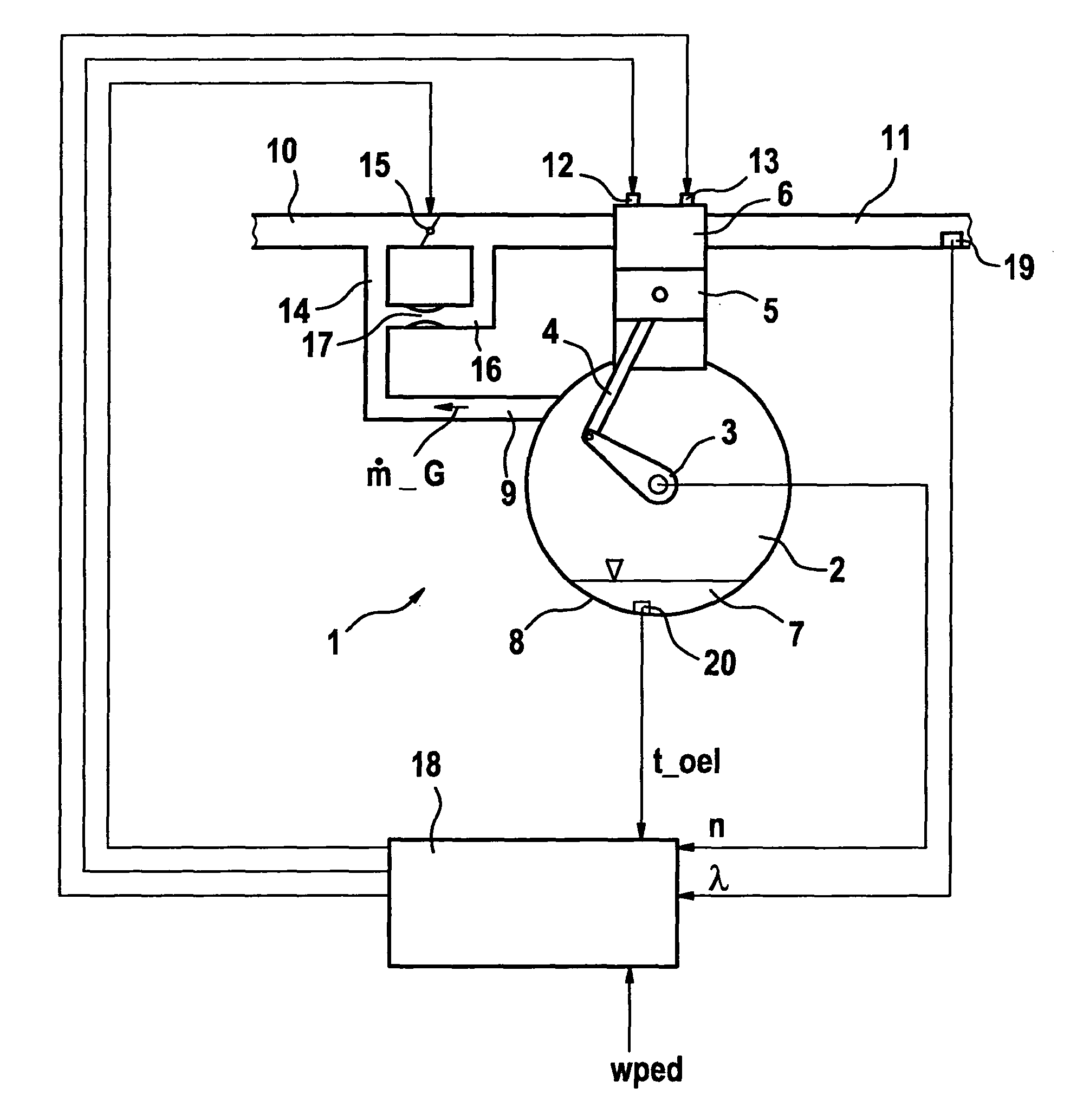
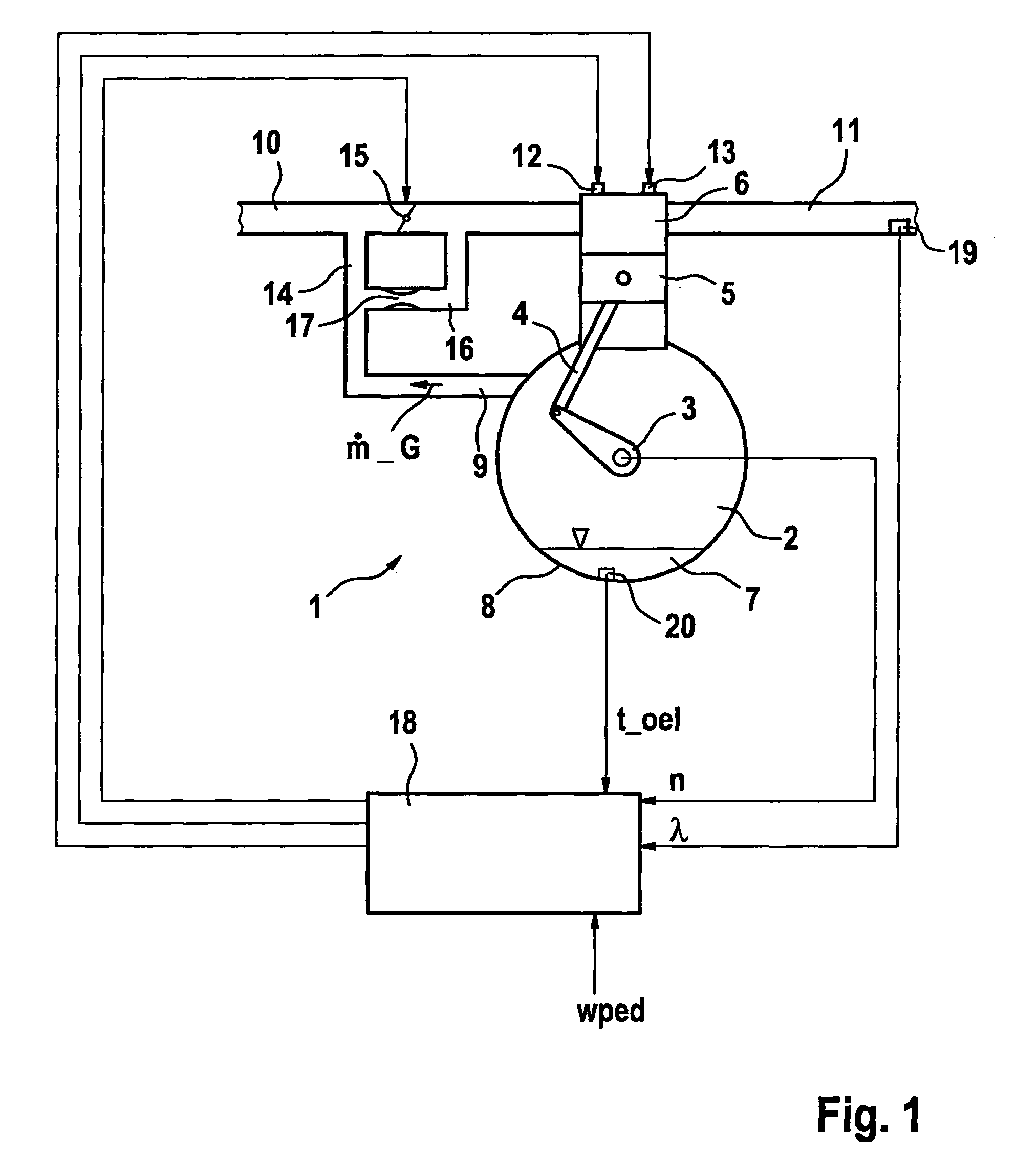
[0022]FIG. 1 is a sketch of an internal combustion engine 1 having a crankcase 2 in which a crankshaft 3 is disposed. Crankshaft 3 is connected via a connecting rod 4 to a piston 5 that is disposed movably back and forth on cylinder 6. For simplicity's sake, only one cylinder of the internal combustion engine is depicted here; the internal combustion engine usually possesses several, for example four or six, cylinders. Present in crankcase 2 is engine oil 7 that is delivered, via conduits and pumps not depicted here, to the respective lubrication points, among others the running surface of piston 5 in cylinder 6. The engine oil collects in an oil sump 8. In order to dissipate excess pressure in crankcase 2, the latter is connected via a vent 9 to intake section 10 of the internal combustion engine. Ambient air is aspirated in known fashion via intake section 10 into cylinder 6, and combustion gases are discharged back into the environment via a schematically depicted exhaust system ...


PUM


Abstract

In a method for operating an internal combustion engine, a crankcase of the internal combustion engine has a vent into the intake section of the internal combustion engine, and upon outgassing of fuel out of engine oil present in the crankcase, the operating point of the internal combustion engine is modified so that the air-fuel ratio does not fall below a definable value.

Description

BACKGROUND OF THE INVENTION[0001]1. Field of the Invention[0002]The present invention relates to a method for operating an internal combustion engine, in which a crankcase of the internal combustion engine has a vent into the intake section of the internal combustion engine.[0003]2. Description of Related Art[0004]The crankcase of an internal combustion engine is not permanently sealed. A small amount of gas flows past the piston rings and, without an opening in the crankcase, would create a high pressure therein. This pressure buildup is avoided by way of the so-called crankcase vent. The crankcase vent directs gases out of the crankcase into the intake duct and thus into the intake section of the internal combustion engine. A direct connection to intake duct vacuum is avoided, since otherwise the crankcase would be brought to the pressure level of the intake duct.[0005]Not only are combusted “blow-by” gases pushed via the piston rings into the crankcase, but also, especially when ...

Claims


Application Information

Patent Timeline
Patent Type & Authority Patents(United States)
IPC IPC(8): F02D41/14
CPCF02D37/02F02D41/003F02D41/40F02D41/0002F02D41/047Y02T10/44F02D41/12F02D2250/22F02D41/08Y02T10/40
Inventor MALLEBREIN, GEORGVLAD, CRINAREITER, JOCHEN
Owner ROBERT BOSCH GMBH
Why Eureka
Try Eureka