Sheet conveyance device and image forming apparatus using the same device

a conveyancing device and image forming technology, applied in the direction of transportation and packaging, thin material processing, article separation, etc., can solve the problems of large device, high cost, and inability to easily separate sheets, and achieve the effect of simplifying the structure of the device and the apparatus, reducing manufacturing costs, and high reliability

Active Publication Date: 2013-08-13
KONICA MINOLTA BUSINESS TECH INC
View PDF14 Cites 2 Cited by
  • Summary
  • Abstract
  • Description
  • Claims
  • Application Information

AI Technical Summary

Benefits of technology

[0007]To solve the above problems, the present invention is designed to offer a sheet conveyance device and an image forming apparatus, exhibiting reduced manufacturing cost, but at high reliability, wherein to simplify the structure of said device and apparatus, the number of the structuring parts is reduced compared to that of conventional devices, whereby the overall size of the device is downsized.

Problems solved by technology

However, these sheets exhibit a higher contacting force between each sheet, so that sheets are not easily separated, and consequently, superposed sheets are too often conveyed.
However, since the above patent application includes the timing pulley to form a pucker on the sheet, the device becomes quite large and complicated.
Further, the production cost of the device itself increases.

Method used


Image

  • Sheet conveyance device and image forming apparatus using the same device
  • Sheet conveyance device and image forming apparatus using the same device
  • Sheet conveyance device and image forming apparatus using the same device

Examples


embodiment 1

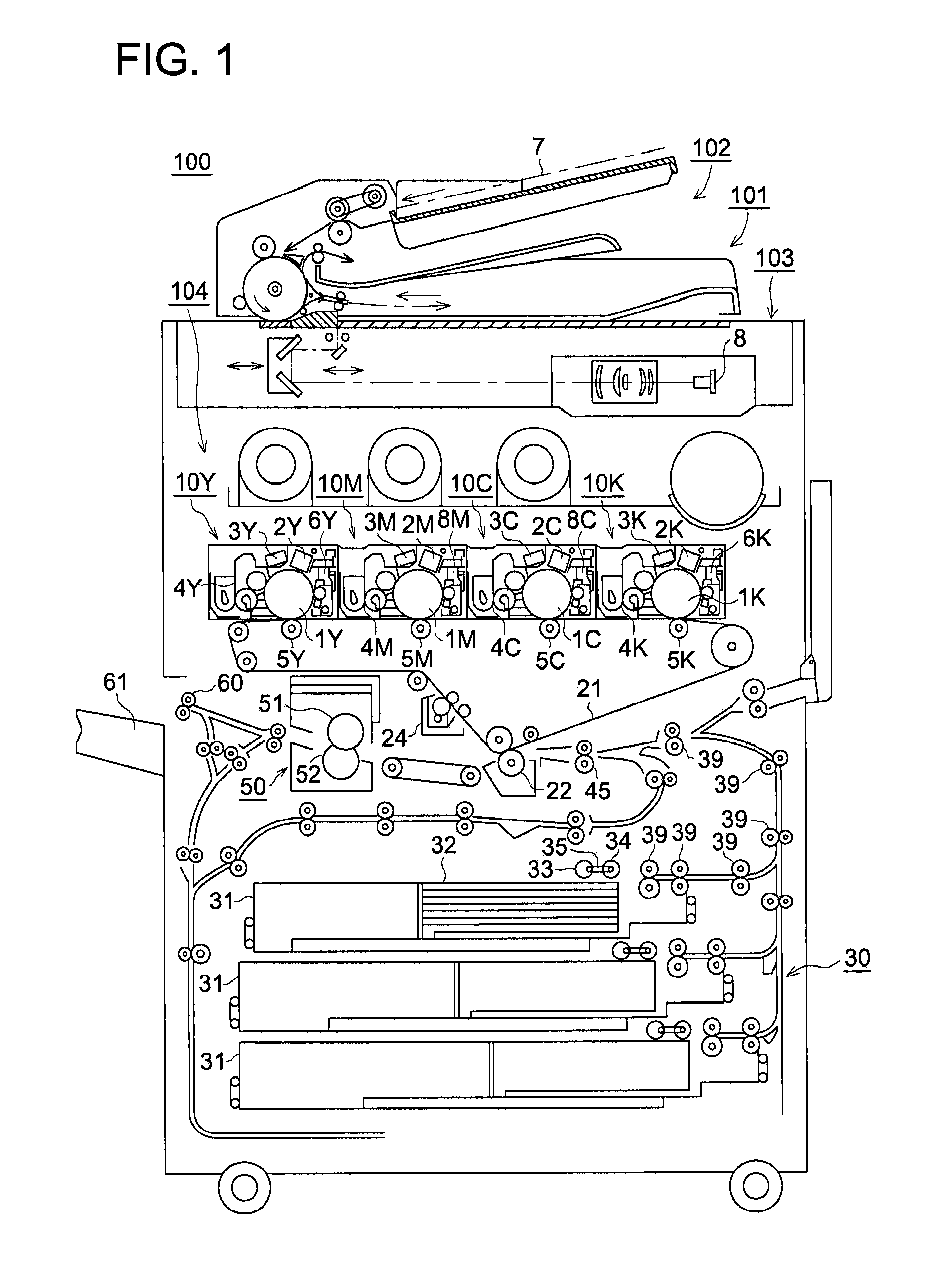
[0039]FIG. 1 is a schematic drawing to show a constitutional example of image forming apparatus 100, relating to Embodiment 1 of the present invention. In FIG. 1, image forming apparatus 1 is structured of image forming section 104, image reading device 101, sheet conveyance device 30, and image fixing device 50. Image forming section 104 is referred to as a tandem type full color image forming section, said image forming section 104 is structured of image forming units 10Y, 10M, 10C and 10K, intermediate transfer body 21, secondary transfer section 22, and cleaning section 24 to clean intermediate transfer body 21.

[0040]Image reading device 101, structured of automatic document feeding device 102, and scanning exposure device 103, is provided above image forming section 104. Original document 7, placed on a platen of automatic document feeding device 102, is conveyed by a conveyance section, which is not illustrated. Images, formed on a single surface or both surfaces of original d...

embodiment 2

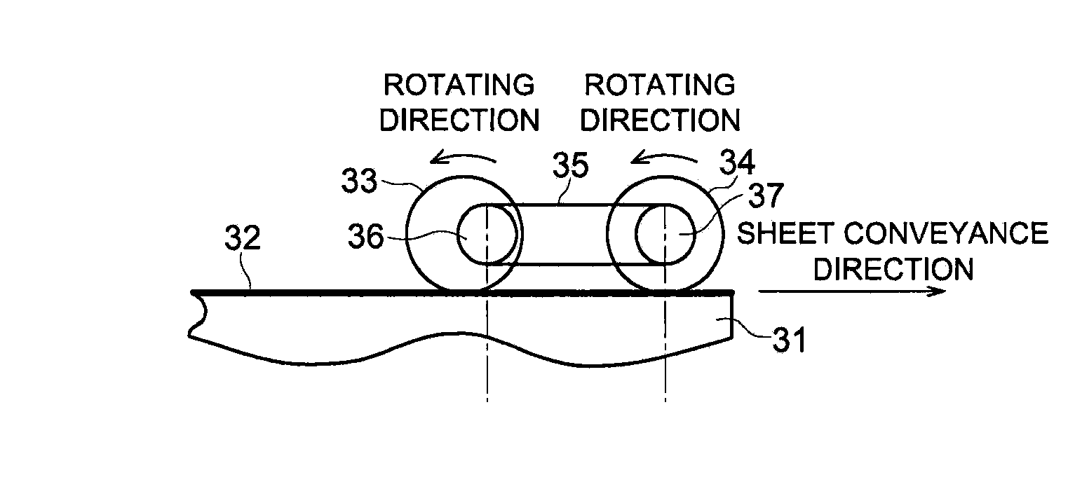
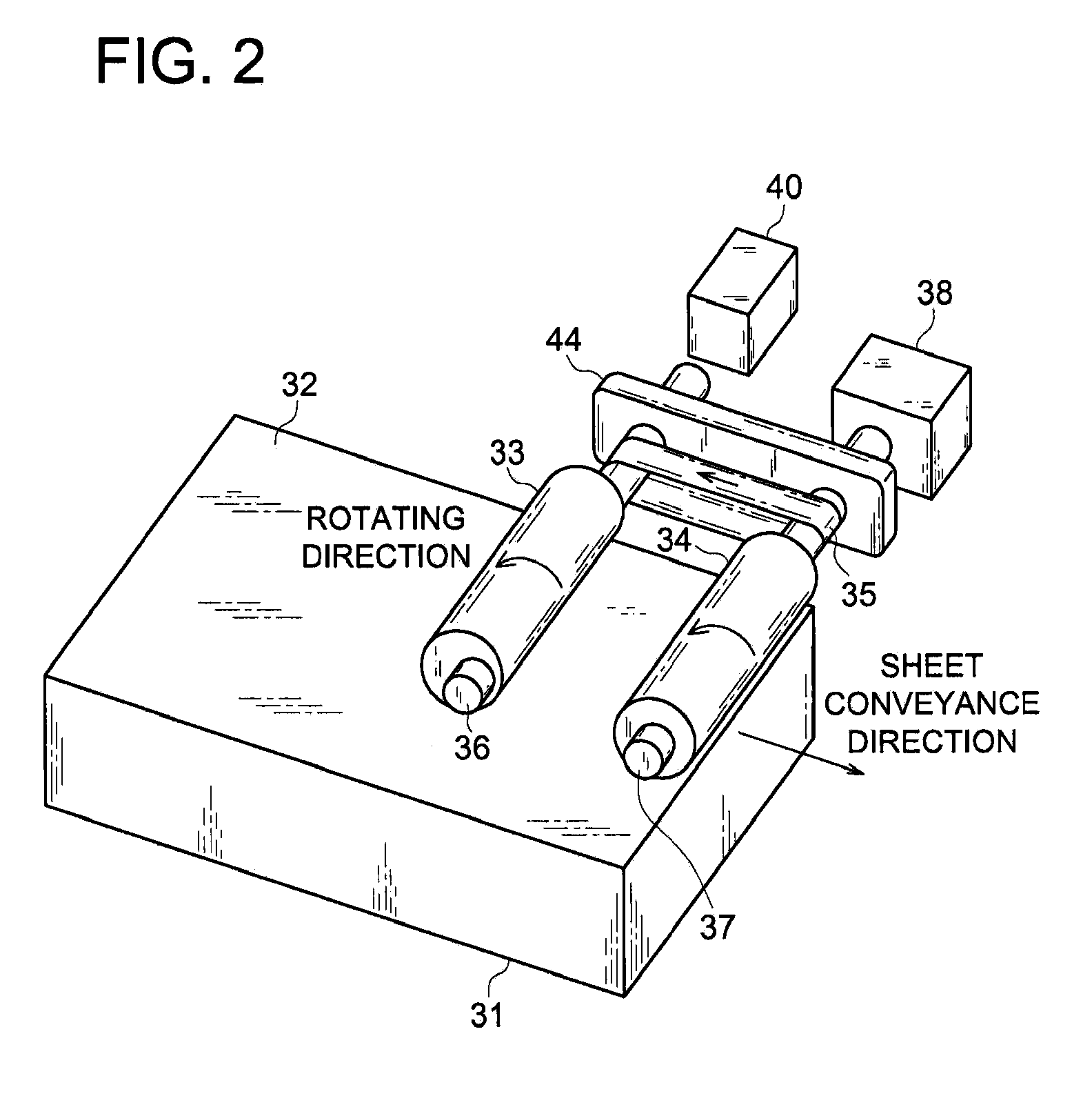
[0075]FIGS. 6A-6E show the operational example of sheet conveyance device 30A, relating to In those figures, sheet conveyance device 30A is structured of conveyance roller 33A, eccentric roller 34A, and coupling belt 35.

[0076]In FIGS. 6A-6E, eccentric roller 34A goes through a full rotation. That is, when drive motor 38 is rotated counterclockwise, which motor is connected to roller shaft 36A, conveyance roller 33A rotates counterclockwise, and eccentric roller 34A, coupled with conveyance roller 33A by coupling belt 35, also rotates counterclockwise. Since the peripheral velocity of eccentric roller 34A differs from that of conveyance roller 33A, sheet 32 is puckered between eccentric roller 34A and conveyance roller 33A, as is desired.

[0077]In FIG. 6A, concerning eccentric roller 34A, the center of eccentric roller shaft 37A is at a position which is shifted to the left from the center of a peripheral circle of eccentric roller 34A. Said position represents a pucker-forming stand...

embodiment 3

[0086]FIGS. 7A-7E show the example of the operation of sheet conveyance device 308 relating to Sheet conveyance device 308 is structured of a first eccentric roller (hereinafter referred to as “eccentric roller 33B”), a second eccentric roller (hereinafter referred to as “eccentric roller 34B”), and coupling belt 35.

[0087]In FIGS. 7A-7E, when drive motor 38 (being not illustrated), which is connected to a first eccentric shaft (hereinafter referred to as “eccentric roller shaft 36B”), rotates counterclockwise, so that eccentric roller 33B also rotates counterclockwise, and a second eccentric roller shaft (hereinafter referred to as “eccentric roller shaft 37B”), coupled by coupling belt 35, also rotates, so that eccentric roller 34B likewise rotates counterclockwise. Since the peripheral velocity of eccentric roller 338 differs from that of eccentric roller 34B, sheet 32 is puckered between eccentric roller 33B and eccentric roller 343. Alternatively, drive motor 38 may be coupled ...


PUM

PropertyMeasurementUnit
distanceaaaaaaaaaa
peripheral lengthaaaaaaaaaa
lengthaaaaaaaaaa

Abstract

A sheet conveyance device to convey a sheet which is stored within a sheet storing section, including: a plurality of sheet conveyance rollers, mounted on a sheet storing section, to be parallel to each other with respect to rotating centers, wherein the plurality of the sheet conveyance rollers come into contact with the sheet to convey the sheet toward an exterior of the sheet conveyance device; and a coupling section to couple the plurality of the sheet conveyance rollers and to rotate the plurality of the sheet conveyance rollers, wherein at least one of the plurality of the sheet conveyance rollers represents an irregularly shaped roller, wherein the irregularly shaped roller is coupled to another sheet conveyance roller by the coupling section, and wherein a distance between a rotation center and a peripheral surface of the irregularly shaped roller is inconstant, in a rotational direction of the irregularly shaped roller.

Description

CROSS REFERENCE TO RELATED APPLICATION[0001]This application is based on Japanese Patent Application No. 2008-306,708 filed on Dec. 1, 2008 with the Japanese Patent Office, the entire content of which is hereby incorporated by reference.TECHNICAL FIELD[0002]The present invention relates to a sheet conveyance device, having a function in which a sheet is puckered between rollers so that the uppermost sheet is separated from a bundle of sheets, and said device being applicable to printers, copying machines, or associated image forming apparatuses, and in particular, relates to an image forming apparatus, using the same sheet conveyance device.BACKGROUND ART[0003]In recent years, since image printing technologies have been improved, images can be formed on various media, such as normal sheets, coated sheets, and sheets used for OHP (being an overhead projector). However, these sheets exhibit a higher contacting force between each sheet, so that sheets are not easily separated, and cons...

Claims


Application Information

Patent Timeline
Patent Type & Authority Patents(United States)
IPC IPC(8): B65H3/06
CPCB65H3/0676B65H2301/51212B65H2404/1116
Inventor KAWACHI, KUNIHIROMIZUNO, KYOICHIMATSUO, MASAHIRO
Owner KONICA MINOLTA BUSINESS TECH INC
Why Eureka
Try Eureka