Fluid distribution in radial flow reactors including moving bed reactors

a technology of radial flow reactors and moving beds, which is applied in the direction of sustainable manufacturing/processing, physical/chemical process catalysts, organic chemistry, etc., to achieve the effect of reducing or eliminating the induction of high localized fluid velocity

Active Publication Date: 2013-08-13
UOP LLC
View PDF2 Cites 5 Cited by
  • Summary
  • Abstract
  • Description
  • Claims
  • Application Information

AI Technical Summary

Benefits of technology

[0009]The present invention is directed to apparatuses and methods for contacting radially flowing fluids with a solid particulate that address the issues noted above. These include difficulties encountered industrially with conventional catalyst retention devices, for example profile wire screens in which the individual wires are assembled with the catalyst contacting side having a smaller area (e.g., per unit of axial height) relative to the opposing side that does not contact catalyst. The invention is associated with the recognition that high pressure drop across radial flow reactors, progressing to catalyst plugging and leading to screen damage, is attributed to the formation of fluid jets that directly impinge on the catalyst. Particle retention devices for radial flow contacting apparatuses (e.g., reactors), as described herein, are therefore commercially advantageous in that they reduce or eliminate the induction of high localized fluid velocities, or fluid jets, which detrimentally interact with discreet portions of a dense solid particulate phase such as a downwardly moving catalyst bed.
[0010]Embodiments of the invention are directed to particle retention devices, as described herein, having a larger area facing a particle retention zone than the opposing area facing a zone that does not contain solid particulate, such as either a fluid inlet distribution zone or a fluid outlet collection zone. This configuration beneficially increases the area of initial contact (e.g., in the case of an outer screen with inwardly flowing fluid) and / or final contact (e.g., in the case of an inner screen with inwardly flowing fluid) between the radially flowing fluid and solid particulate. The expanded area provided, for fluids entering or exiting these critical areas through flow channels passing in the radial direction through the particle retention devices, thereby reduces the impinging velocity at interfaces between these devices and solid particulate.
[0014]Particle retention devices, as described herein, therefore provide improved fluid flow characteristics and also effectively contain a solid particulate such as a catalyst. Additional embodiments of the invention are therefore directed to such particle retention devices, in which profile wire or another type of circumferentially elongated particle retention element is used to form a plurality of flow channels having widths, at a surface adjacent to a particle retention zone, exceeding respective smallest widths, either at the opposing surface or within the flow channels. Further embodiments are directed to radial flow reactors comprising such a particle retention device or devices (e.g., both an outer and an inner screen), and still further embodiments are directed to hydrocarbon conversion processes utilizing the radial flow reactors.

Problems solved by technology

These include difficulties encountered industrially with conventional catalyst retention devices, for example profile wire screens in which the individual wires are assembled with the catalyst contacting side having a smaller area (e.g., per unit of axial height) relative to the opposing side that does not contact catalyst.

Method used


Image

  • Fluid distribution in radial flow reactors including moving bed reactors
  • Fluid distribution in radial flow reactors including moving bed reactors
  • Fluid distribution in radial flow reactors including moving bed reactors

Examples


Embodiment Construction

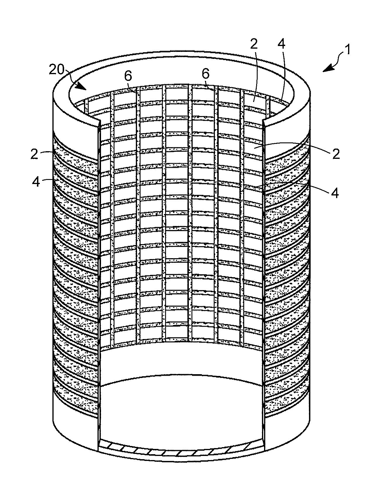
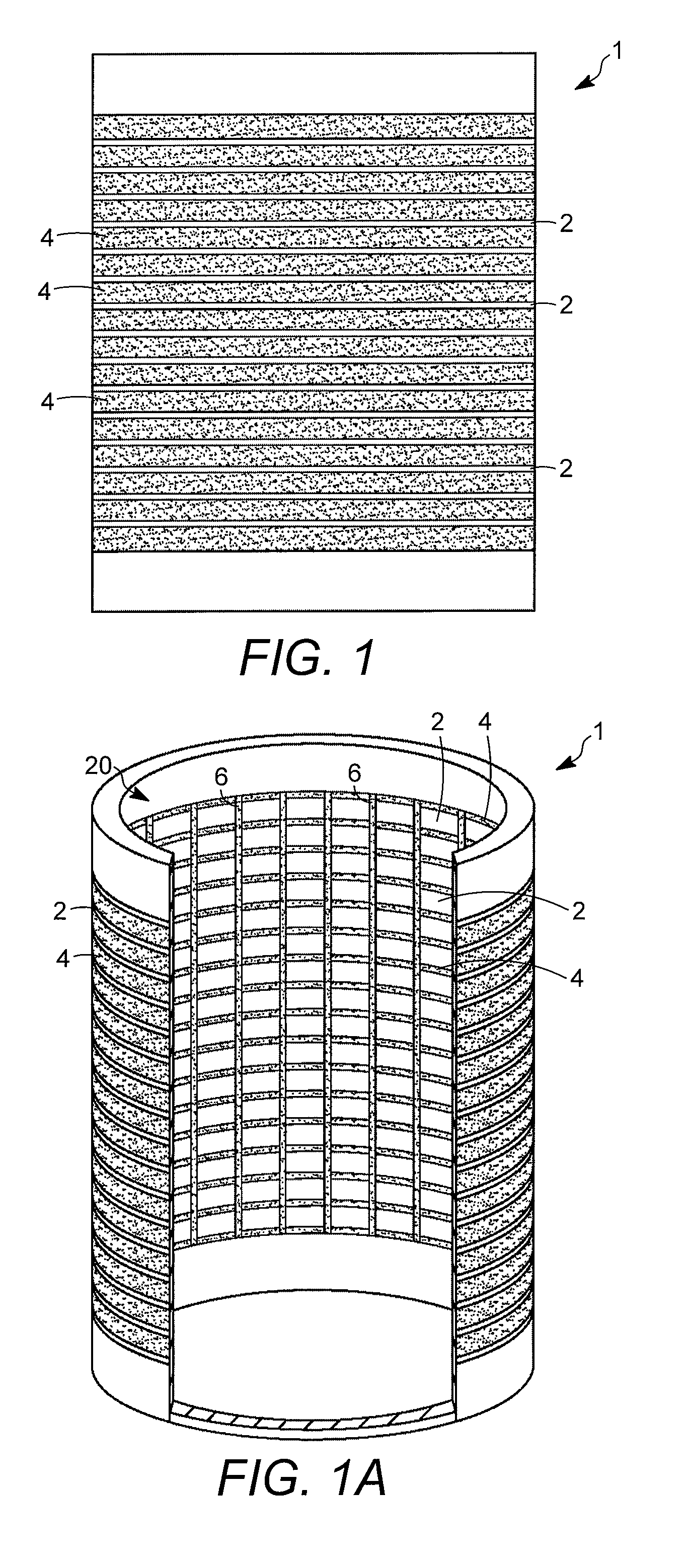
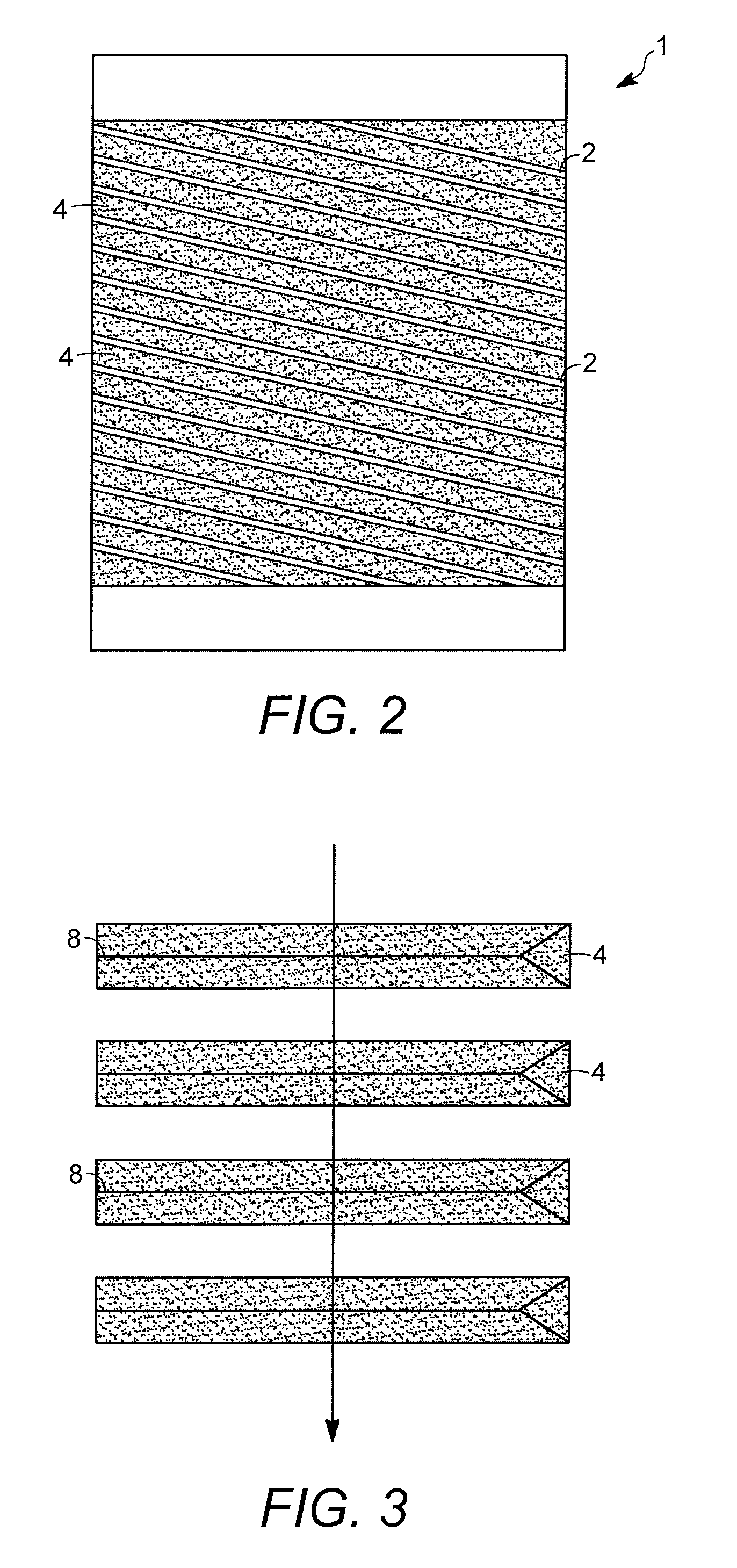
[0030]Aspects of the invention relate to particle retention devices for use in apparatuses for contacting fluids (e.g., gases, liquids, or mixed phase fluids containing both gas and liquid fractions) with solids that are typically in particulate form (e.g., spheres, pellets, granules, etc.). The maximum dimension (e.g., diameter of a sphere or length of a pellet), for an average particle of such particulate solids, is typically in the range from about 0.5 mm (0.02 inches) to about 15 mm (0.59 inches), and often from about 1 mm (0.04 inches) to about 10 mm (0.39 inches). An exemplary solid particulate is a catalyst used to promote a desired hydrocarbon conversion reaction and normally containing a catalytically active metal or combination of metals dispersed on a solid, microporous carrier. Catalysts and other solid particulates are retained in particle retention devices when the smallest widths of the flow channels, for passage of fluid in the radial direction, are less than the sma...


PUM

PropertyMeasurementUnit
lengthaaaaaaaaaa
lengthaaaaaaaaaa
widthsaaaaaaaaaa

Abstract

Apparatuses and methods for contacting radially flowing fluids with a solid particulate (e.g., catalyst) with reduced tendency to form fluid jets that impinge on the solid particulate, leading to solid attrition and plugging, are described. Representative particle retention devices for use in these apparatuses and methods have flow channels passing therethrough, from a first surface to an opposing second surface that is adjacent to a particle retention zone. Widths of the flow channels at this opposing second surface will exceed their smallest flow channel widths.

Description

FIELD OF THE INVENTION[0001]The present invention relates to the use of particle retention devices such as outer and / or inner screens in radial flow reactors that improve fluid distribution and provide other important advantages, for example with respect to catalyst movement in the case of moving bed reactors.DESCRIPTION OF RELATED ART[0002]A wide variety of industrial applications involve radial or horizontal flow apparatuses for contacting a fluid with a solid particulate. Representative processes include those used in the refining and petrochemical industries for hydrocarbon conversion, adsorption, and exhaust gas treatment. In reacting a hydrocarbon stream in a radial flow reactor, for example, the feed to be converted is normally at least partially vaporized when it is passed into a solid particulate catalyst bed to bring about the desired reaction. Over time, the catalyst gradually loses its activity, or becomes spent, due to the formation of coke deposits on the catalyst surf...

Claims


Application Information

Patent Timeline
Patent Type & Authority Patents(United States)
IPC IPC(8): C10G35/04C07C5/32B01J8/02
CPCB01J8/0214B01J8/0221B01J8/12B01J8/24C10G35/04B01J2208/00884B01J8/085Y02P20/10
Inventor SENETAR, JOHN J.
Owner UOP LLC
Why Eureka
Try Eureka