Method for operating an internal combustion engine

a technology of internal combustion engine and internal combustion engine, which is applied in the direction of machines/engines, electric control, instruments, etc., can solve the problems of significant transient power loss, and achieve the effect of fast load increas

Inactive Publication Date: 2013-08-20
AVL LIST GMBH
View PDF11 Cites 4 Cited by
  • Summary
  • Abstract
  • Description
  • Claims
  • Application Information

AI Technical Summary

Benefits of technology

[0004]It is the object of the present invention to avoid the above disadvantage and to permit fast load increase at medium engine speeds.
[0006]Depending on the load demand the control valve is controlled by means of a transient characteristic map or via a transient function. In the steady-state case, however, the control valve is controlled by means of a steady-state characteristic map. Thus it will be ensured that the switch from low-pressure turbocharger to high-pressure turbocharger is effected adaptively, avoiding a loss of load in transient operation.
[0008]If the low-pressure exhaust gas turbine has a bypass line with a wastegate, it is of particular advantage if the wastegate is controlled in transient operation by means of a transient characteristic map or via a transient function. Control of the control valve of the high-pressure exhaust gas turbine and of the wastegate of the low-pressure exhaust gas turbine thus is coordinated and is effected via transient functions or transient characteristic maps. It is thus ensured that the transition from high-pressure turbocharger to low-pressure turbocharger occurs at optimum speed.

Problems solved by technology

If the turbochargers have different sizes there is danger that in the transient case load increase at medium engine speeds is too slow due to the inertia of the larger turbocharger, which will result in significant transient power losses.

Method used


Image

  • Method for operating an internal combustion engine
  • Method for operating an internal combustion engine
  • Method for operating an internal combustion engine

Examples


Embodiment Construction

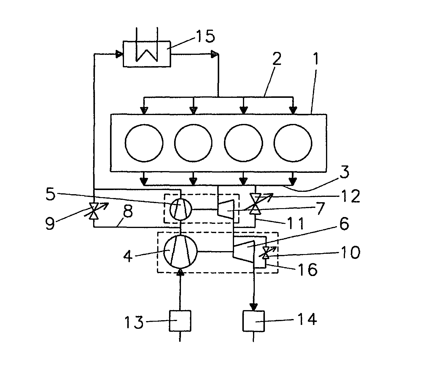
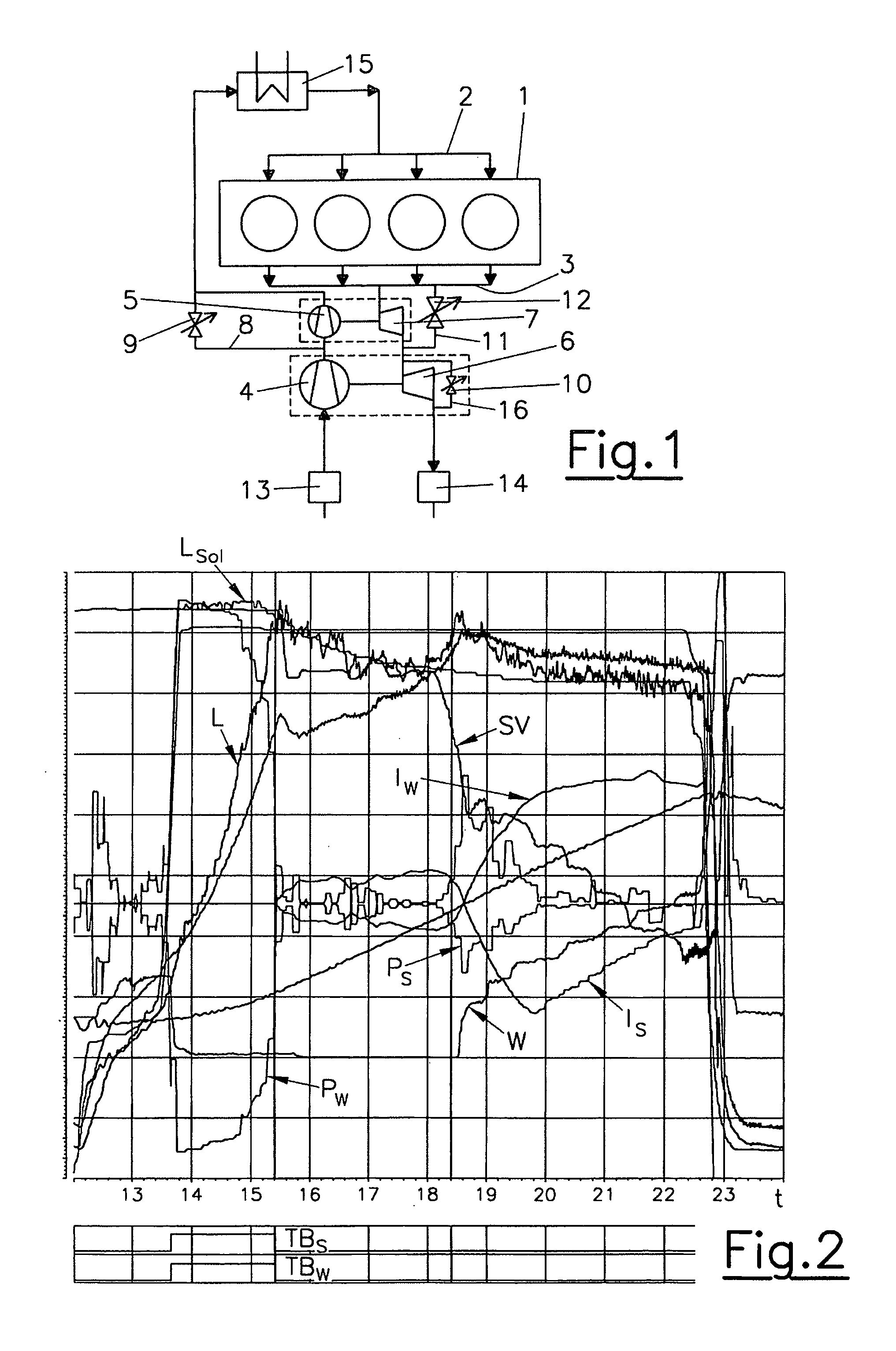
[0019]FIG. 1 schematically shows an internal combustion engine 1 with an intake system 1 and an exhaust system 3. The internal combustion engine 1 has two-stage turbocharging with a low-pressure compressor 4 and a high-pressure compressor 5, the low-pressure compressor 4 being driven by a low-pressure exhaust gas turbine 6, the high-pressure compressor by a high-pressure exhaust gas turbine 7. The high-pressure compressor 5 can be by-passed by means of a bypass line 8, in which a flap 9 is disposed. The high-pressure exhaust gas turbine 7 can be bypassed by means of a bypass line 11 provided with a control valve 12. A bypass line 16 containing a wastegate 10 is provided for by-passing the low-pressure exhaust gas turbine 6.

[0020]An air filter is provided upstream of the low-pressure compressor 4. Reference numeral 14 indicates an exhaust treatment device in the exhaust line 3, for instance a catalytic converter.

[0021]Intake air is fed to the internal combustion engine 1 via the low-...


PUM


Abstract

The invention relates to a method for operating an internal combustion engine (1) with two-stage turbocharging by a low-pressure exhaust gas turbine (6) and a high-pressure exhaust gas turbine (7), the low-pressure exhaust gas turbine (6) being positioned downstream of the high-pressure exhaust gas turbine (7) in the exhaust system (3) of the internal combustion engine (1), and the high-pressure exhaust gas turbine (7) being provided with a bypass line (11) with a control valve (12). In order to achieve quick response of the internal combustion engine (1) in transient operation, it is provided that continuously or periodically at certain intervals preferably an electronic control unit will check whether a steady-state or a transient operating state of the internal combustion engine (1) is prevailing, and that the control valve (12) is controlled in accordance with at least one steady-state characteristic map (32, 33) in the steady-state case and in accordance with at least one transient characteristic map (31) or a transient function in the transient case.

Description

BACKGROUND OF THE INVENTION[0001]The invention relates to a method of operating an internal combustion engine with two-stage turbocharging by a low-pressure exhaust gas turbine and a high-pressure exhaust gas turbine, the low-pressure exhaust gas turbine being positioned downstream of the high-pressure exhaust gas turbine in the exhaust system of the internal combustion engine, and the high-pressure exhaust gas turbine being provided with a bypass line including a control valve.DESCRIPTION OF PRIOR ART[0002]From DE 10 2004 005 945 B4 a method is known for boost pressure control in an internal combustion engine with two-stage exhaust gas turbocharging with a first and a second turbocharger whose compression power may be individually adjusted by an adjusting element. Depending on charging pressure target values, presetting values for the adjusting elements of the turbochargers are computed. Furthermore, depending on the control difference between actual charging pressure and charging ...

Claims


Application Information

Patent Timeline
Patent Type & Authority Patents(United States)
IPC IPC(8): F02B33/00
CPCF02D41/0007F02D41/2422F02B37/013F02B37/18F02D41/18F02D2041/1409F02D2250/21Y02T10/144Y02T10/12
Inventor KAPUS, PAUL
Owner AVL LIST GMBH
Why Eureka
Try Eureka