Polymer electrolyte fuel cell and method for measuring voltages of cells in polymer electrolyte fuel cell

a technology of polymer electrolyte and fuel cell, which is applied in the direction of cell components, instruments, material electrochemical variables, etc., can solve the problems of difficult to simply and surely measure the voltage of each cell, and large number of operation steps, so as to prevent heat release via the voltage measuring terminal and ensure maintenance

Inactive Publication Date: 2013-08-20
PANASONIC CORP
View PDF15 Cites 0 Cited by
  • Summary
  • Abstract
  • Description
  • Claims
  • Application Information

AI Technical Summary

Benefits of technology

[0047]In accordance with the polymer electrolyte fuel cell and the method for measuring the voltages of the cells in the polymer electrolyte fuel cell according to the present invention, the voltages of the cells can be monitored without detaching the covering member covering the cell stack, and the malfunction of the fuel cell system can be specified on site for maintenance. In addition, since the voltage measuring terminals are not inserted into the voltage terminal insertion holes at any time other than the time when the voltage terminal insertion holes are used for maintenance, the heat release via the voltage measuring terminals can be prevented.
[0048]Further, in accordance with a fuel cell system including the polymer electrolyte fuel cell of the present invention, the maintenance can be efficiently and surely carried out.

Problems solved by technology

However, it has conventionally been difficult to simply and surely measure the voltage of each cell.
In addition, measuring the voltage of each cell is difficult because since the cell stack is formed by stacking a large number of cells, the voltage measuring terminals need to be attached to all the cells, and this requires a large number of operation steps.

Method used


Image

  • Polymer electrolyte fuel cell and method for measuring voltages of cells in polymer electrolyte fuel cell
  • Polymer electrolyte fuel cell and method for measuring voltages of cells in polymer electrolyte fuel cell
  • Polymer electrolyte fuel cell and method for measuring voltages of cells in polymer electrolyte fuel cell

Examples


embodiment 1

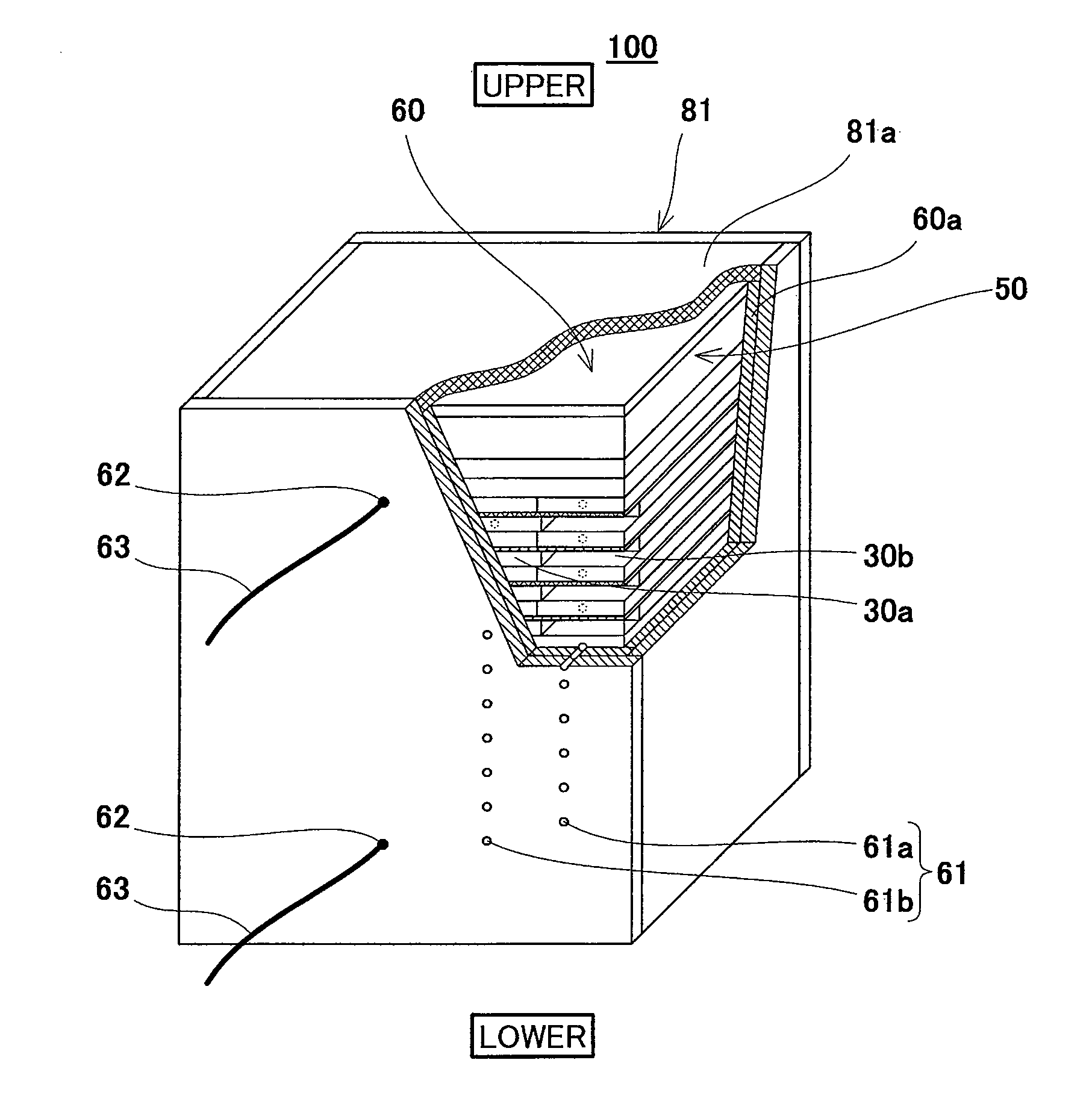
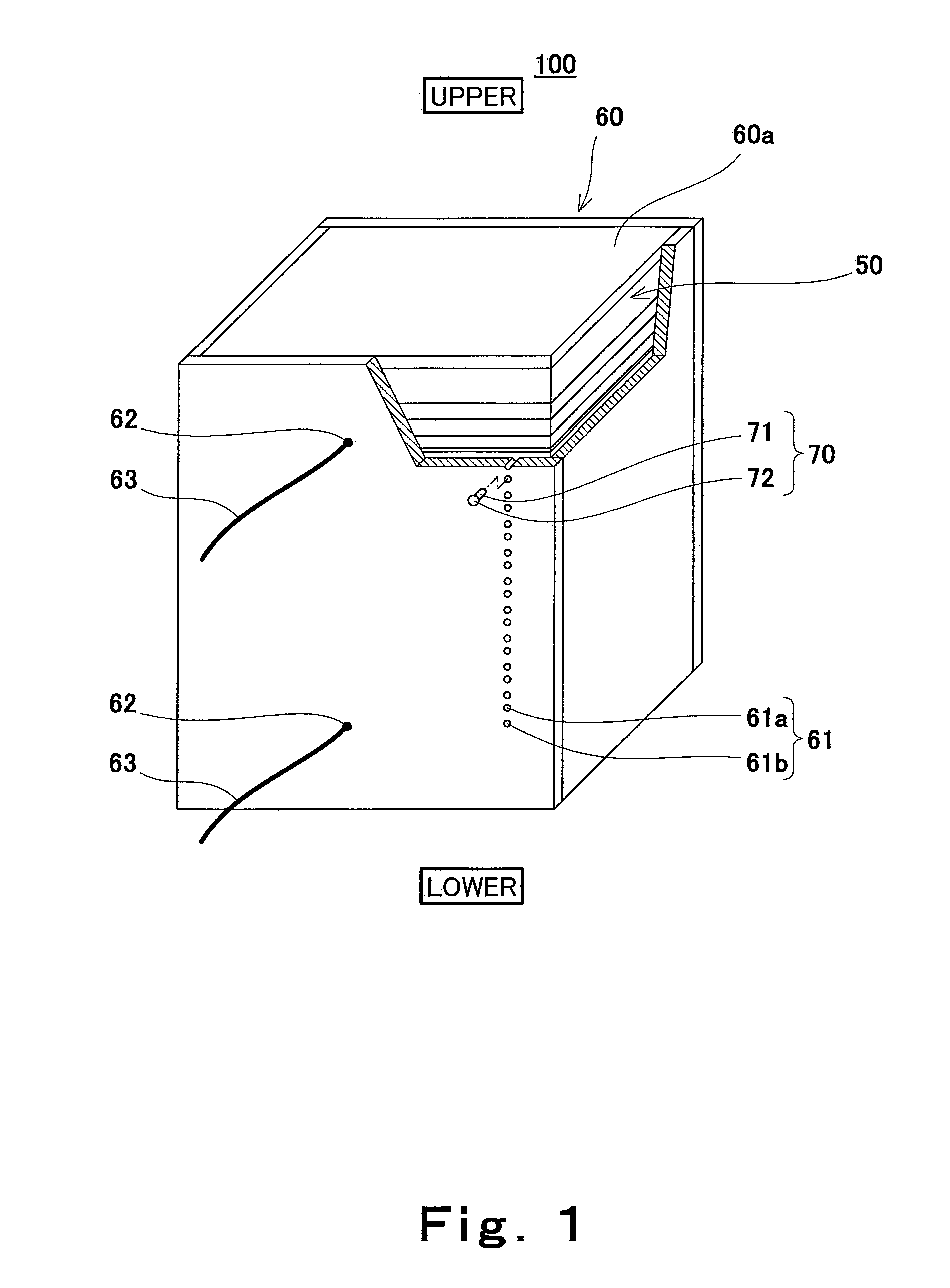
[0128]FIG. 1 is a perspective view schematically showing a schematic configuration of a polymer electrolyte fuel cell according to Embodiment 1 of the present invention. In FIG. 1, a part of the polymer electrolyte fuel cell is cut away to show an internal structure thereof, and a vertical direction of the polymer electrolyte fuel cell is shown as a vertical direction of the drawing.

[0129]As shown in FIG. 1, a polymer electrolyte fuel cell (hereinafter referred to as “PEFC”) 100 according to Embodiment 1 includes a cell stack 50, a heat insulating casing 60, and stopper members 70.

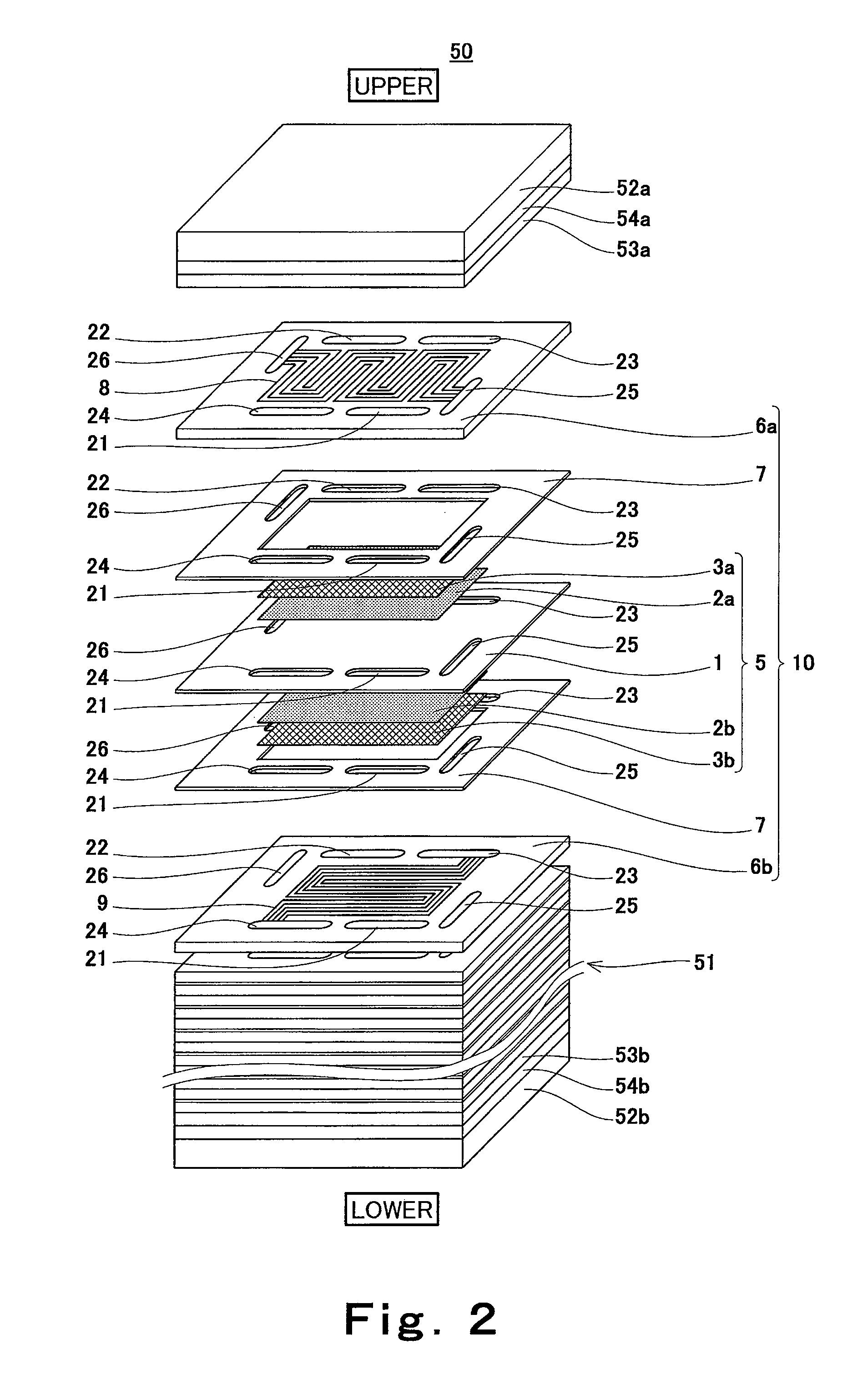
[0130]First, the cell stack 50 will be explained in reference to FIG. 2.

[0131]FIG. 2 is a developed view schematically showing the cell stack 50 and cells constituting the cell stack 50 in the PEFC 100 shown in FIG. 1. In FIG. 2, a part of the cell stack 50 is omitted, and a vertical direction of the cell stack 50 is shown as a vertical direction of the drawing.

[0132]As shown in FIG. 2, the cell stack 50 i...

modification example 1

[0155]FIG. 3 is a perspective view schematically showing a schematic configuration of Modification Example 1 of the PEFC 100 according to Embodiment 1. In FIG. 3, a vertical direction of the PEFC 100 is shown as a vertical direction of the drawing.

[0156]As shown in FIG. 3, the voltage measuring terminal insertion hole 61 of the PEFC 100 of Modification Example 1 is constituted by a voltage measuring terminal insertion hole 61c and a voltage measuring terminal insertion hole 61d. The voltage measuring terminal insertion hole 61c is a through hole formed on the heat insulating plate 60a and has a circular cross-sectional shape. The voltage measuring terminal insertion hole 61d is a through hole formed on the heat insulating plate 60a and has a diamond cross-sectional shape. A pair of the voltage measuring terminal insertion holes 61c and 61d are arranged in the stack direction of the cells 10 in the cell stack body 51, and are formed at positions respectively corresponding to the anod...

modification example 2

[0159]FIG. 4 is a perspective view schematically showing a schematic configuration of Modification Example 2 of the PEFC 100 according to Embodiment 1. In FIG. 4, a vertical direction of the PEFC 100 is shown as a vertical direction of the drawing.

[0160]As shown in FIG. 4, in the PEFC 100 according to Modification Example 2, the voltage measuring terminal insertion hole 61 is constituted by voltage measuring terminal insertion holes 61e and 61f which are different from each other in size (cross-sectional area). With this, it is possible to prevent the voltage measuring terminal from being mistakenly inserted into the incorrect hole when carrying out the maintenance (when measuring the voltage of each cell 10).

[0161]Moreover, the size of the cross-sectional shape of the main body portion 71 of the stopper member 70 (not shown in FIG. 4) corresponds to the size of the opening of the voltage measuring terminal insertion hole 61e or 61f. With this, the heat release from each voltage mea...


PUM

PropertyMeasurementUnit
electrically-conductiveaaaaaaaaaa
voltageaaaaaaaaaa
voltagesaaaaaaaaaa

Abstract

A polymer electrolyte fuel cell of the present invention includes: plate-shaped cells (10) each having a pair of plate-shaped separators (6a) and (6b) and a membrane-electrode assembly (5) disposed between the separators (6a) and (6b); a cell stack (50) configured by stacking and fastening the cells (10); and a covering member (60) covering a peripheral surface of the cell stack (50), and voltage measuring terminal insertion holes (61) used to measure the voltages of the cells (10) are formed on the covering member (60) so as to be located at positions corresponding to the separators (6a) and (6b) of the cells (10).

Description

RELATED APPLICATIONS[0001]This application is the U.S. National Phase under 35 U.S.C. §371 of International Application No. PCT / JP2008 / 000980, filed on Apr. 14, 2008, which in turn claims the benefit of Japanese Application No. 2007-123661, filed on May 8, 2007, the disclosures of which applications are incorporated by reference herein.TECHNICAL FIELD[0002]The present invention relates to a polymer electrolyte fuel cell and a method for measuring voltages of cells in the polymer electrolyte fuel cell, and particularly to a configuration for maintenance of the polymer electrolyte fuel cell.BACKGROUND ART[0003]A polymer electrolyte fuel cell (hereinafter referred to as “PEFC”) causes a hydrogen-containing fuel gas and an oxygen-containing oxidizing gas, such as air, to electrochemically react with each other to generate electric power and heat at the same time. A unit cell (cell) of the PEFC includes: an MEA (Membrane-Electrode-Assembly; a polymer electrolyte layer-electrode stack bod...

Claims


Application Information

Patent Timeline
Patent Type & Authority Patents(United States)
IPC IPC(8): H01M8/04
CPCH01M8/0247H01M8/04552H01M8/1002H01M8/241H01M8/2475H01M8/04671H01M8/04679H01M8/04686H01M8/248H01M2008/1095Y02E60/521H01M8/0263H01M8/1007H01M8/2483Y02E60/50
Inventor SHIBATA, SOICHIKUSAKABE, HIROKI
Owner PANASONIC CORP
Why Eureka
Try Eureka