
System for managing the heat fluxes of an aircraft

a technology for managing systems and aircraft, applied in the direction of machines/engines, lighting and heating apparatus, energy-saving board measures, etc., can solve the problems of complex channels, heavy weight, and low reliability of aircraft, and achieve the effect of reducing the energy consumption of propulsion systems, reducing the cost of aircraft maintenance, and improving the efficiency of aircraft maintenan

Inactive Publication Date: 2013-08-27
AIRBUS OPERATIONS (SAS)
View PDF21 Cites 2 Cited by
  • Summary
  • Abstract
  • Description
  • Claims
  • Application Information

AI Technical Summary

Benefits of technology

The patent proposes a system to manage the heat of an aircraft to reduce drag and energy consumption. The system aims to eliminate the limitations of current systems that have limited operating periods.

Problems solved by technology

To the extent that the air intakes always interfere with the aerodynamic flow, the cooling air channels prove to be detrimental in terms of aerodynamic drag for the aircraft and therefore in terms of energy consumption of the propulsion systems.
However, whereby their dimensions are calculated based on the most significant requirements, their impact on the aerodynamic drag, and therefore on the consumption of the aircraft, is significant during the high-speed flight phases, whereas the requirements are normally low for these flight phases.
According to another variant, the cooling air channels have a variable geometry to adapt their dimensions based on requirements, but in this case, the channels prove complex, heavy, and not very reliable.
However, this solution is not completely satisfactory because its operating period is limited to the extent where it is no longer possible to dissipate the heat in the tanks when the fuel temperature reaches a certain threshold linked to the fuel temperature that is accepted by the turbomachines or to the risks of inflammability of the tank.
Actually, it is necessary to ensure that a breakdown that appears at the cell and disrupts the operation of the propulsion systems is extremely improbable.

Method used


Image

  • System for managing the heat fluxes of an aircraft
  • System for managing the heat fluxes of an aircraft
  • System for managing the heat fluxes of an aircraft

Examples


Embodiment Construction

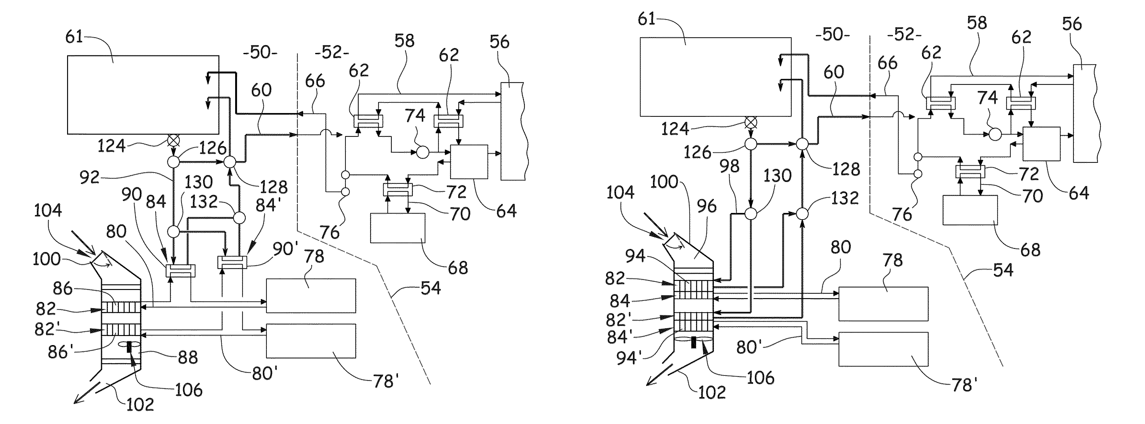
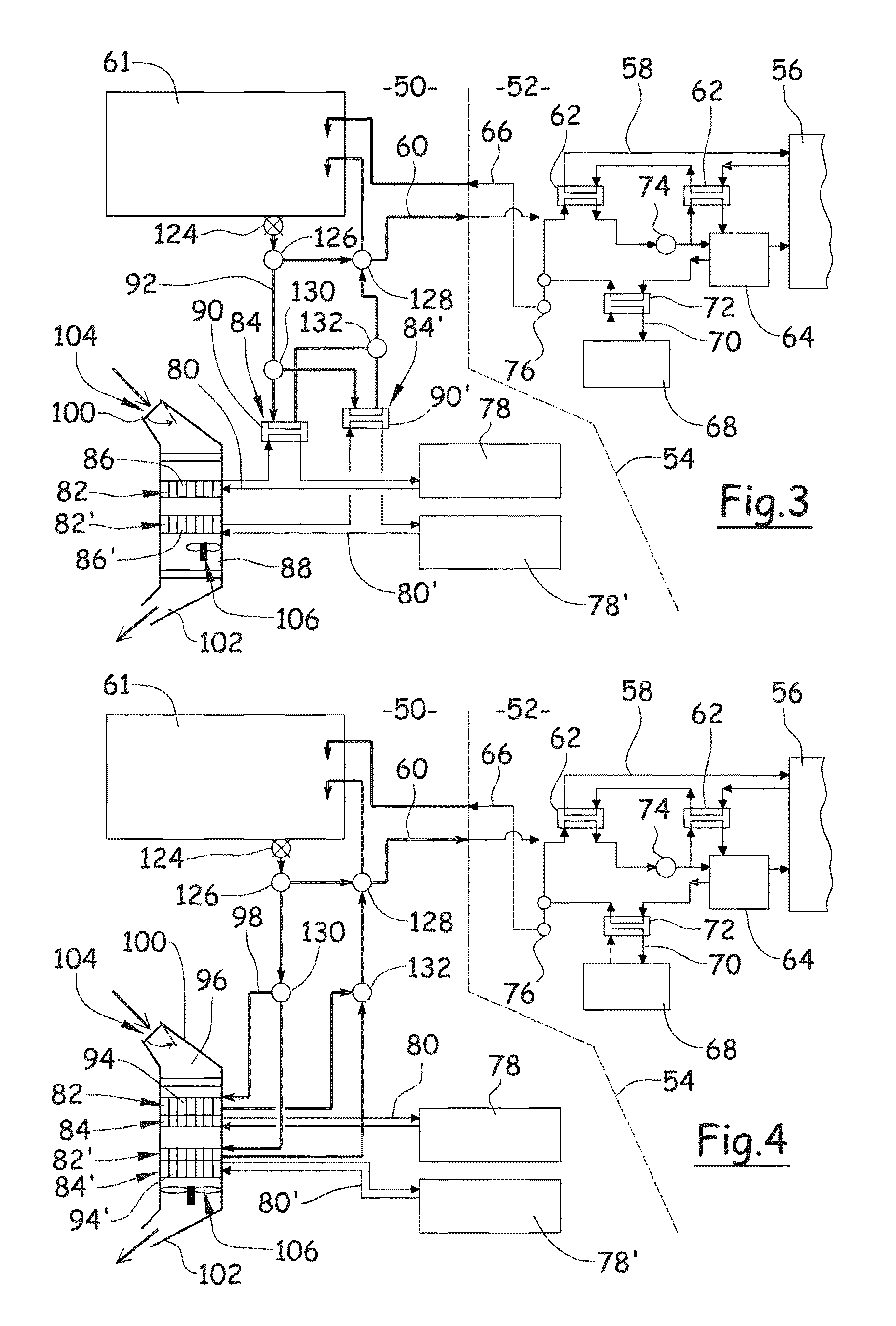
[0038]FIGS. 3 and 4 diagrammatically show an aircraft with a cell 50 and at least one propulsion system 52.

[0039]Cell is broadly defined as all of the elements of the aircraft, in particular the fuselage, the wings, and the tail assemblies, with the exception of the propulsion systems.

[0040]According to a widely used embodiment, a propulsion system is suspended under a wing by means of a mast. More generally, the propulsion system is connected to the cell by means of an interface 54 that is embodied by dotted lines in FIGS. 3 and 4.

[0041]A propulsion system 52 comprises a turbomachine 56 that is equipped with a first engine cooling circuit 58, in which a coolant, in particular oil, circulates.

[0042]The turbomachine 56 is supplied with fuel by means of a fuel supply circuit 60 that extends from at least one tank 61 that is arranged at the cell.

[0043]To ensure the cooling of the coolant of the engine cooling circuit 58, said circuit 58 comprises at least one first engine exchanger 62....


PUM


Abstract

A system for managing heat fluxes of an aircraft is provided, including a fuel tank supplying a turbomachine with fuel via a fuel supply circuit; a cell cooling circuit connected to a thermal effluents source, which integrates a first heat exchanger ensuring heat transfer between a coolant circulating in the cell cooling circuit and air flow channeled into a cooling air channel extending from an air intake to an exhaust; and a second heat exchanger ensuring a heat transfer between the coolant circulating in the cell cooling circuit and the fuel. The air intake includes a blocker to open / close it. The system includes a fuel transfer circuit, which connects the fuel tank to the second heat exchanger and provides fuel to the second heat exchanger, including a valve selectively changing a fuel supply direction from the second heat exchanger between the directions of the tank and the fuel supply circuit.

Description

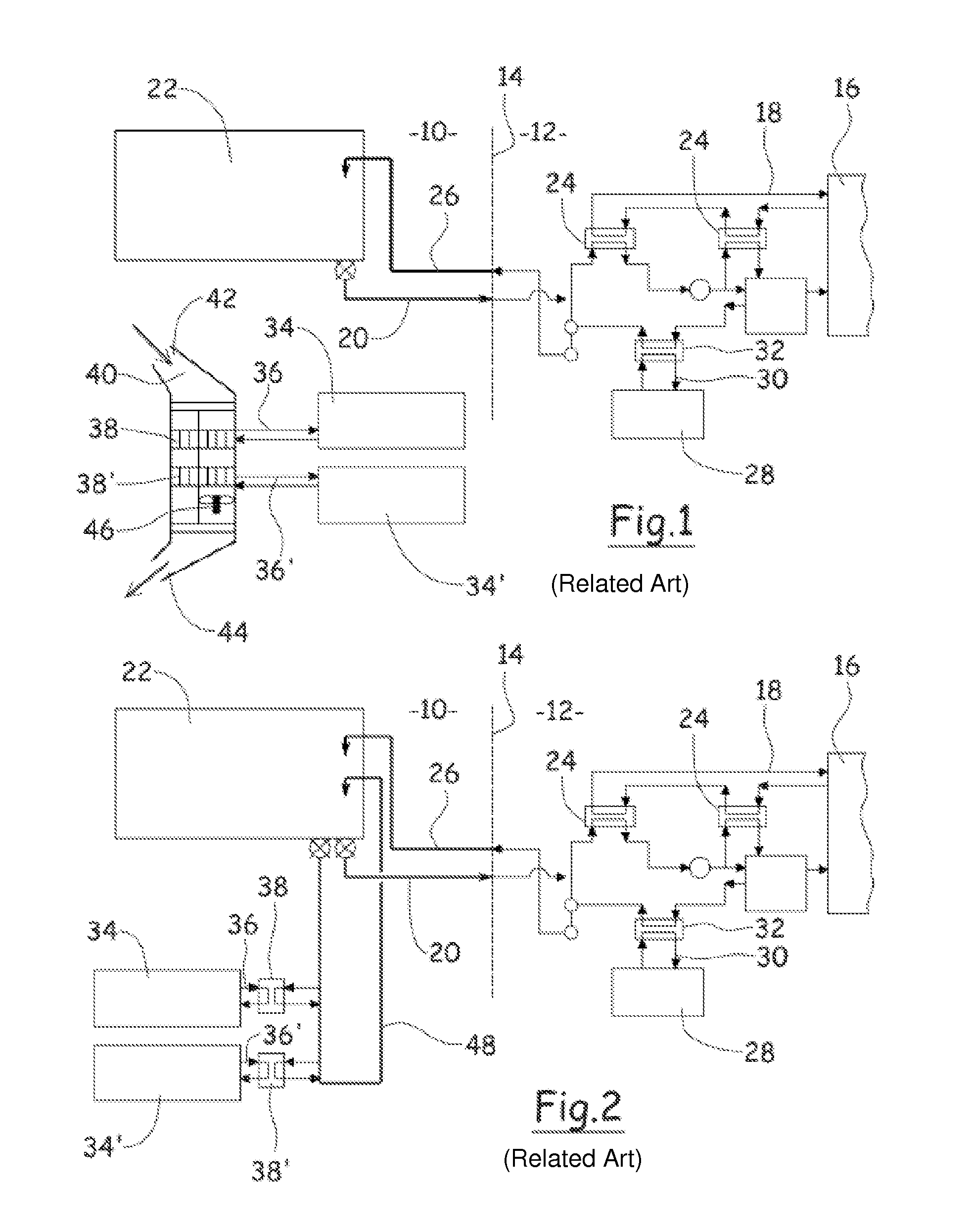
BACKGROUND OF THE INVENTION[0001]1. Field of the Invention[0002]This invention relates to a system for managing heat fluxes of an aircraft.[0003]2. Description of the Related Art[0004]An aircraft comprises a cell and at least one propulsion system. In FIGS. 1 and 2, a cell was shown diagrammatically at 10 and a propulsion system was shown diagrammatically at 12.[0005]According to a widely used embodiment, a propulsion system is suspended under a wing by means of a mast. More generally, the propulsion system is connected to the cell by means of an interface 14 that is embodied by dotted lines in FIGS. 1 and 2.[0006]A propulsion system 12 comprises a turbomachine 16 that is equipped with a first engine cooling circuit 18, in which a coolant, in particular oil, circulates.[0007]The turbomachine is supplied with fuel by means of a fuel circuit 20 that extends from a tank 22 that is arranged at the cell. As illustrated in FIG. 1, it is possible to use several cooling sources to cool the ...

Claims


Application Information

Patent Timeline
Patent Type & Authority Patents(United States)
IPC IPC(8): F02K99/00
CPCB64D13/06B64D37/34B64D2013/0674F28D1/024F28F27/02Y02T50/56F28D21/00Y02T50/50
Inventor BULIN, GUILLAUME
Owner AIRBUS OPERATIONS (SAS)
Learn More