Laminating device and thermal pressure bonding and conveying device used in laminating device

a technology of conveying device and laminating device, which is applied in the direction of mechanical control device, process and machine control, instruments, etc., can solve the problems of heating means going out of control, devices have drawbacks, etc., and achieve the effect of reducing fluctuation in temperature, increasing the rate of rise of laminating temperature, and ensuring stability

Inactive Publication Date: 2013-08-27
SAKAE CO LTD
View PDF7 Cites 3 Cited by
  • Summary
  • Abstract
  • Description
  • Claims
  • Application Information

AI Technical Summary

Benefits of technology

[0021]Thanks to the temperature self-controlling function of the platelike heating member with PTC thermistors, the target laminating temperature can be maintained without causing an overheat, without having to use a temperature control system (temperature sensors, temperature adjuster, temperature controller). Further, when compared with an intermittent on-off control by a temperature adjuster, the temperature self-control of this invention is based on continuous changes in resistance, minimizing fluctuations in temperature.
[0022]Further, because of the temperature characteristic of the platelike heating member with PTC thermistors, the rate of rise of the laminating temperature is fast and the laminating temperature is prevented from exceeding the set temperature. This contributes to an energy conservation and also eliminates the need to take preventive measures against abnormalities.
[0023]Furthermore, since the platelike PTC thermistors produce heat from their entire surfaces, there are few temperature variations with no local temperature changes, realizing a uniform heat distribution in the thermal pressure bonding and conveying device.
[0024]According to the invention of claim 2, the platelike heating member with PTC thermistors can be held firmly and the heat produced by the platelike heating member can easily be transferred to the hollow roll-shaped bond-and-convey member.
[0025]According to the invention of claim 3, the heat from either the front or back surface of the platelike heating member can be transmitted almost uniformly to the hollow roll-shaped bond-and-convey member.
[0026]According to the invention of claim 4, the heat from both the front and back surfaces of the platelike heating member can be transmitted almost uniformly to the hollow roll-shaped bond-and-convey member.

Problems solved by technology

These devices, however, have drawbacks.
In addition, there is a possibility of the heating means going out of control during the heating operation.

Method used


Image

  • Laminating device and thermal pressure bonding and conveying device used in laminating device
  • Laminating device and thermal pressure bonding and conveying device used in laminating device
  • Laminating device and thermal pressure bonding and conveying device used in laminating device

Examples


embodiment 1

Laminating Device

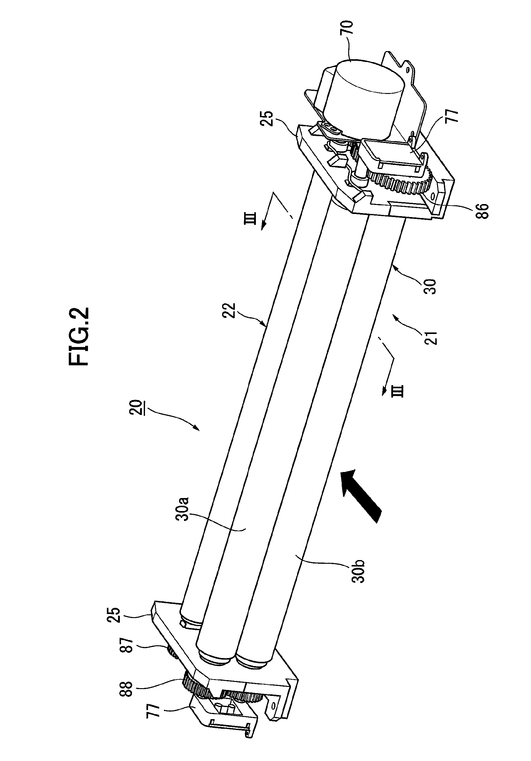
[0061]FIG. 2 and FIG. 3 show an embodiment 1 of the laminating device to which this invention is applied.

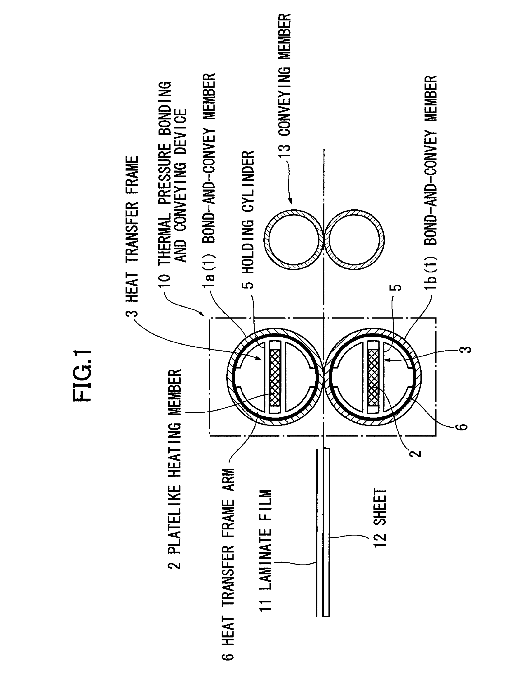
[0062]In the figure, the laminating device 20 comprises a thermal pressure bonding and conveying device 21 that thermally pressure-bonds a laminate film 101 and a sheet 102 while conveying them, stacked together; and a pair of conveying rolls 22 installed downstream of the thermal pressure bonding and conveying device 21 in the sheet conveying direction. The laminating device 20 supports the laminate film and sheet by support side plates 25 of the device frame.

[0063]In this embodiment, the thermal pressure bonding and conveying device 21 is constructed of a pair of thermal pressure bonding and conveying rolls 30 (30a, 30b: also referred to simply as bonding rolls).

[0064]This paired structure of the bonding rolls 30 has a pair of bond-and-convey rolls 31, both formed hollow and adapted to hold between them the laminate film 101 and the sheet 102 as they are convey...

embodiment 2

[0117]FIG. 12 shows an outline of embodiment 2 of the laminating device applying the present invention.

[0118]In the figure, the laminating device 20 comprises a plurality of pairs (in this example, 3 pairs) of bonding rolls 30 (30(1), 30(2), 30(3)) as the thermal pressure bonding and conveying device 21; and a pair of conveying rolls 22 installed downstream of the bonding rolls 30 in the sheet transfer direction to pull and convey the laminated sheet 102.

[0119]The individual paired bonding rolls 30 are constructed in the similar manner to the embodiment 1. Between the individual pairs of bonding rolls 30 and between the last pair of bonding rolls 30 and the paired conveying rolls 22 there are installed guide members 26, as necessary, that guide the laminated sheet 102. Constitutional elements that are identical with the corresponding elements of embodiment 1 are given like reference numerals and their detailed explanations are omitted here.

[0120]With this embodiment, since a plurali...

embodiment 3

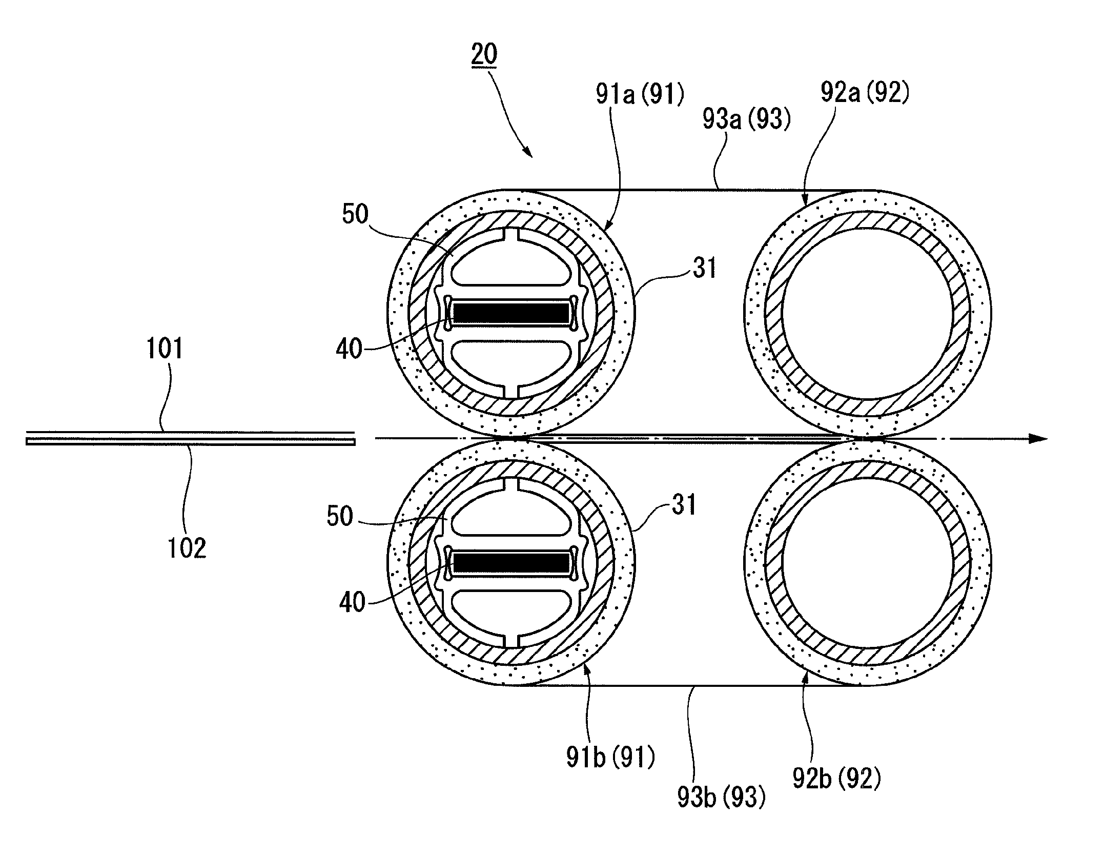
[0121]FIG. 13 shows an outline of embodiment 3 of the laminating device applying the present invention.

[0122]In the figure, unlike embodiment 1 and 2, the laminating device 20 comprises a pair of upstream bond-and-convey rolls 91 (91a, 91b), formed hollow, to grip and convey the laminate film 101 and the sheet 102; a pair of downstream bond-and-convey rolls 92 (92a, 92b), also formed hollow and installed downstream of the upstream bond-and-convey rolls 91, to grip and convey the laminate film 101 and the sheet 102; and belt members 93 (93a, 93b) of polyimide, each stretched between the upstream and downstream bond-and-convey rolls 91 and 92, with the heater assembly 40 installed in each of the paired upstream bond-and-convey rolls 91.

[0123]In this embodiment, the upstream bond-and-convey rolls 91 practically work as the bonding rolls 30 of embodiment 2. The laminated sheet 102 that has passed the upstream bond-and-convey rolls 91 is transported, held between the two belt members 93 ...


PUM

PropertyMeasurementUnit
elastic deformationaaaaaaaaaa
thermal pressureaaaaaaaaaa
pressureaaaaaaaaaa

Abstract

A laminating device is provided that can increase the rate of rise of a laminating temperature and keep the laminating temperature stable without using a temperature control system for a heat source. The laminating device for stacking and bonding a laminate film 11 coated with a hot-melt adhesive and a sheet 12 has a thermal pressure bonding and conveying device 10 that thermally pressure-bonds the laminate film 11 and the sheet 12 while stacking and conveying them. The thermal pressure bonding and conveying device 10 comprises: a pair of bond-and-convey members 1, at least one of them formed as a hollow roll, to grip and convey the laminate film 11 and the sheet 12; a platelike heating member 2 having a platelike PTC thermistor and placed in at least one of the paired bond-and-convey members which is formed as a hollow roll; and a heat transfer frame 3 placed inside and in contact with the hollow roll-shaped bond-and-convey member 1, holding the platelike heating member 2 therein and being able to transfer heat from the platelike heating member 2 to the hollow roll-shaped bond-and-convey member 1.

Description

BACKGROUND OF THE INVENTION[0001]1. Field of the Invention[0002]The present invention relates to a laminating device to stack and bond together a laminate film applied with a hot-melt adhesive and a sheet, and more particularly to improvements in a laminating device that thermally pressure-bonds a laminate film and a sheet together as they are conveyed and in a thermal pressure bonding and conveying device used in the laminating device.[0003]2. Background Art[0004]Conventional laminating devices are found, for example, in Japanese Patent No. 3779014 (Embodiment of Invention, FIG. 4 to FIG. 7) and Japanese Patent No. 2901228 (Embodiment, FIG. 3).[0005]Japanese Patent No. 3779014 discloses a laminating device which has a heating source to heat a laminate film, a pair of pressure-bonding rollers to bond the heated laminate film and a sheet material together and sensors to detect a temperature of the heating source and a temperature of the laminate film, and which controls the temperatu...

Claims


Application Information

Patent Timeline
Patent Type & Authority Patents(United States)
IPC IPC(8): B32B37/00
CPCB32B37/0053B32B2037/1223Y10T156/1741
Inventor FUJISHIMA, NOBUOMASUKO, YOSHIOMITOMO, YASUYUKI
Owner SAKAE CO LTD
Why Eureka
Try Eureka