Lighting device, display device and television receiver

a technology of display device and light guide, which is applied in the direction of lighting and heating equipment, television systems, instruments, etc., can solve the problem that the light emitting components cannot be provided outside the light guide members, and achieve the effect of improving brightness

Active Publication Date: 2013-08-27
SHARP KK
View PDF11 Cites 5 Cited by
  • Summary
  • Abstract
  • Description
  • Claims
  • Application Information

AI Technical Summary

Benefits of technology

[0009]With this configuration, light entering the light entrance surface and traveling through the light guide member is reflected at the scattering surface. The reflected light exits to outside of the light guide member through the light exit surface. Because the holding space is formed in the light guide member such that an opening size of the holding portion increases in a direction in which a molding die for forming the holding space is removed. Therefore, the light entrance surface is less likely to be damaged when separating the molding die. The scattering surface with perforation processing is formed by injection molding. However, the light entrance surface is less likely to be damaged due to the injection molding. The infraction direction of light is less likely to be changed at the light entrance surface and improved brightness is achieved.

Problems solved by technology

Depending on the arrangement of the light guide members, the light emitting components may not be able to be provided outside the light guide members.

Method used


Image

  • Lighting device, display device and television receiver
  • Lighting device, display device and television receiver
  • Lighting device, display device and television receiver

Examples


first embodiment

[0027]The first embodiment of the present invention will be explained with reference to FIGS. 1 to 16. In this embodiment, a liquid crystal display device 10 will be explained. X-axes, Y-axes and Z-axes in some figures correspond to each other so as to indicate the respective directions. In FIGS. 4 to 10, the upper side and the lower side correspond to the front-surface side and the rear-surface side, respectively.

[0028]

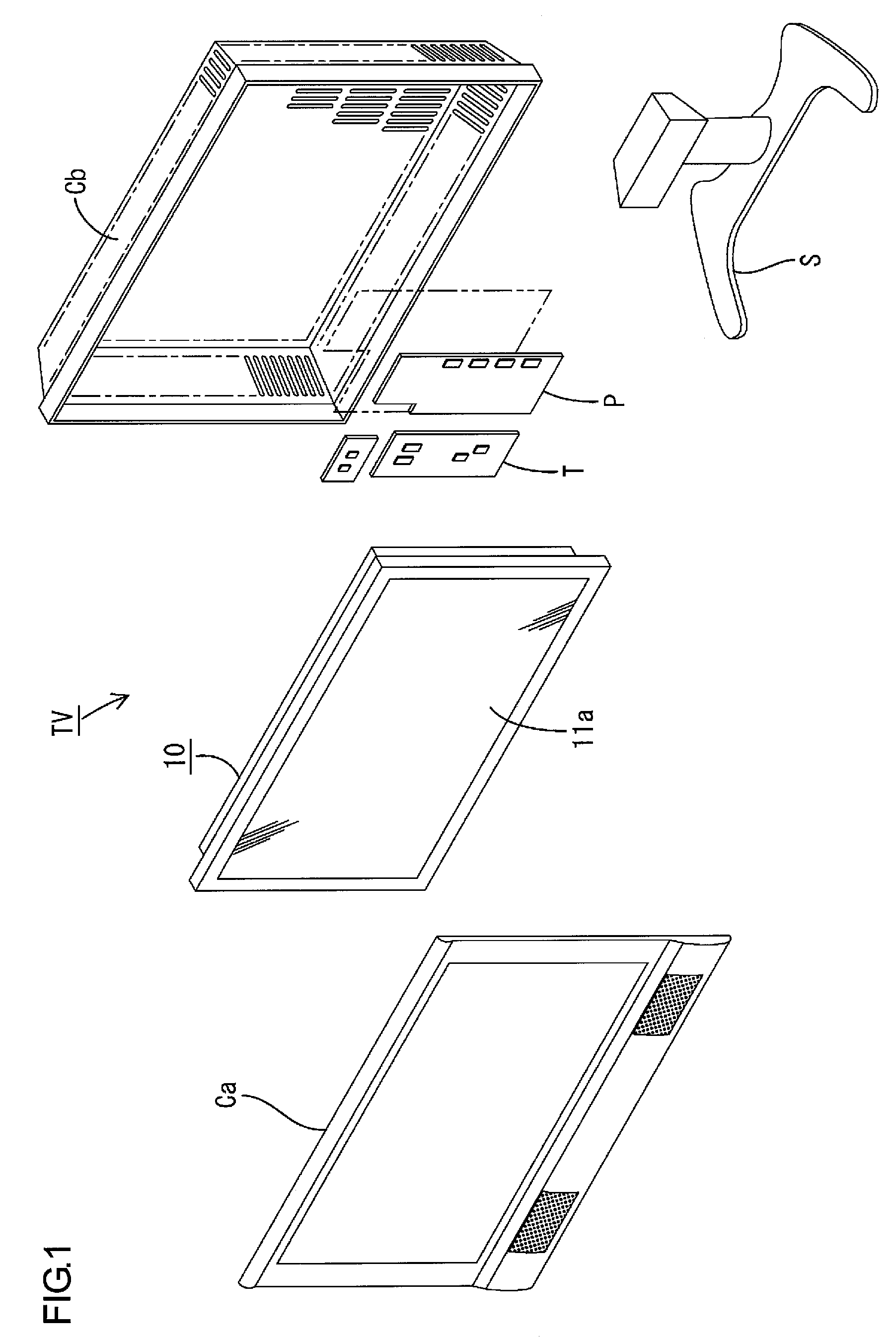
[0029]As illustrated in FIG. 1, the television receiver TV includes the liquid crystal display device 10 (a display device), cabinets Ca and Cb, a power source P, and a tuner T. The cabinets Ca and Cb sandwich the liquid crystal display device 10 therebetween. The liquid crystal display device 10 is housed in the cabinets Ca and Cb. The liquid crystal display device 10 is held by a stand S in a vertical position in which a display surface 11a is set along a substantially vertical direction (the Y-axis direction). The liquid crystal display device 10 has a landscape r...

second embodiment

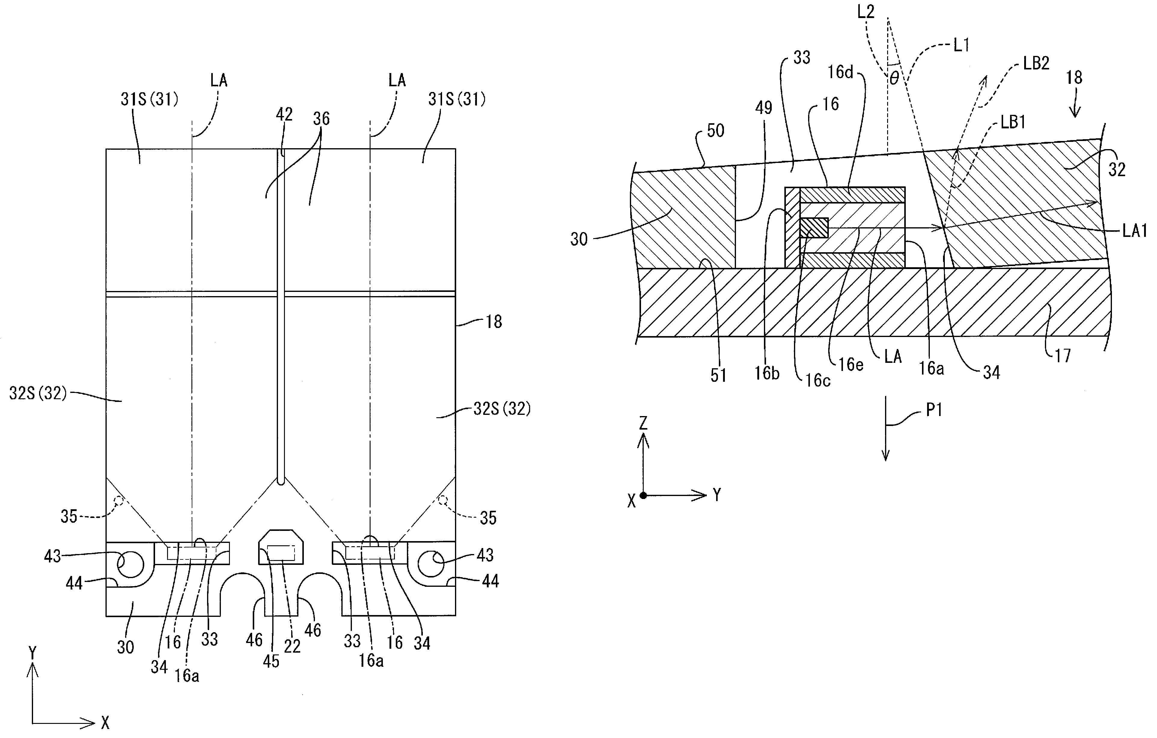
[0105]Next, the second embodiment of the present invention will be explained with reference to FIG. 17. In this embodiment, the LED 16 of the first embodiment is arranged with being inclined. The same components as the first embodiment will be indicated with the same symbols. The same configuration, functions and effects will not be explained.

[0106]In this embodiment, the light emitting surface 16a of the LED 16 is provided to be parallel to the light entrance surface 34. Therefore, the light axis LA of rays of light emitting from the light emitting surface 16a is perpendicular to the light entrance surface 34. Accordingly, the light axis LA of rays of light from the LED 16 is provided on the same line as the light axis LA1 of rays of light traveling through the light guide portion 32. This makes the rays of light from the LED 16 to enter the light entrance surface 34 effectively. In this embodiment, a recess 52 is formed on the surface 51 of the LED board 17 and the LED 16 is fixed...


PUM


Abstract

A lighting device includes an LED 16 and a light guide plate 18 that are fixed to a surface 51 of an LED board 17. The light guide plate 18 includes a light entrance surface 34 that is provided in an LED holding space 33 holding the LED 16 therein, a scattering surface 37 that is formed by performing perforation processing, and a light exit surface 36 through which light exits to outside of the light guide plate 18 after traveling through the light guide plate 18 and reflecting off the scattering surface 37. The LED holding space 33 is formed such that the light guide plate 18 has an opening for the LED holding space 33 and an opening size of the opening increases in a direction P1 in which a lower mold 47B integrally including a projection 47C for forming the LED holding space 33 is removed.

Description

TECHNICAL FIELD[0001]The present invention relates to a lighting device, a display device and a television receiver.BACKGROUND ART[0002]A lighting device disclosed in Patent Document 1 is known as a lighting device used in a display device of a television receiver. The lighting device includes light emitting components and light guide members. Rays of light are emitted from the light emitting components in a direction substantially parallel to a display surface of a liquid crystal panel. The light guide members receive rays of light emitted from the light emitting components and output the rays of light from light exit surfaces to the liquid crystal panel side. A scattering surface is formed on surfaces of the light guide members opposite from the liquid crystal panel by printing a scattering pattern that scatters rays of light.[0003]Depending on the kind of the light guide members, instead of printing the scattering pattern, the surfaces of the light guide members may be processed ...

Claims


Application Information

Patent Timeline
Patent Type & Authority Patents(United States)
IPC IPC(8): F21V7/04
CPCG02B6/0021G02B6/0036G02B6/0046G02B6/008G02B6/0088G02F1/133603
Inventor SHIMIZU, TAKAHARU
Owner SHARP KK
Why Eureka
Try Eureka