Battery

a battery and insulating film technology, applied in the field of batteries, can solve the problems of affecting the insertion efficiency of the battery, so as to reduce the frictional resistance at the time of insertion, improve the insertion efficiency, and wasteful gaps

Active Publication Date: 2013-08-27
TOYOTA JIDOSHA KK
View PDF11 Cites 2 Cited by
  • Summary
  • Abstract
  • Description
  • Claims
  • Application Information

AI Technical Summary

Benefits of technology

[0007]Taking this matter into consideration, and a primary object of the present invention is to provide a battery comprising an electrode assembly and insulating film with improved insertability into the exterior case.
[0009]Thus, by forming the insulating film into a bag shape, the film does not interfere with the corners of the exterior case, and as a result, the film (and electrode assembly) becomes easy to insert into the exterior case. In addition, it is possible to avoid a situation wherein creases and kinks occur in the insulating film, and detrimental effects on battery performance caused by those creases and kinks (e.g., locally poor circulation of electrolyte, etc.) can be prevented beforehand. Furthermore, when the corner members of the exterior case have a rounded shape, because the shape of the insulating film fits that rounded shape, dead space in the corner members is minimized, and the insulating film (and electrode assembly) can be housed efficiently therein.
[0010]In one preferred aspect of the battery disclosed herein, the electrode assembly is formed by winding together a sheet-shaped positive electrode and a sheet-shaped negative electrode with a separator interposed therebetween. The sheet-shaped positive electrode and the sheet-shaped negative electrode respectively have a positive electrode side protruding part and a negative electrode side protruding part that are wound in a protruding manner from the separator. Moreover, the positive electrode side protruding part and the negative electrode side protruding part respectively constitute the end portions of the wound electrode assembly in the direction of the central axis of winding, and the tips of the end portions in the axial direction are bundled into single units. By bundling the tips of the end portions in the axial direction of the wound electrode assembly in this manner, the electrode assembly becomes easy to insert into the bag shaped insulating film.
[0012]In accordance with the above structure, because the insulating film is positioned so as to enclose the tips from both sides, wasteful gaps between the film and the wound electrode assembly (particularly gaps between the film and the tips) can be minimized, and the insertion efficiency improves thereby. Furthermore, the end portions of the insulating film assume a tapered shape, so interference with the corner member at the time of insertion into the exterior case can be reliably prevented.
[0013]In one preferred aspect of the battery disclosed herein, the insulating film is positioned so that the projecting side portions thereof come into contact with opposing inner wall side faces of the exterior case. With such a structure the insulating film (and electrode assembly) can be supported by the faces of the inner walls of the exterior case, and the insulating film (and electrode assembly) can be tightly secured in the case. In comparison with previous insulating films (typically box-shaped), it is possible to reduce the contact points between the film and the inner walls of the case from 4 points (i.e., the 4 points at the corner members) to 2 points (i.e., the 2 points at the projecting side portions), and frictional resistance at the time of insertion can be reduced thereby.
[0014]Preferably, the insulating film surrounding the electrode assembly comprises a single resin sheet that is folded back onto itself, and the edges thereof are formed into the bag shape by bonding mutually opposing sides thereof resulting from the folding. Thus, the electrode assembly can be packaged by an extremely simple construction.

Problems solved by technology

However, there has been a problem because in conventional battery construction the insulating film is in the shape of a box having corners, and that makes it difficult to insert the insulating film (and electrode assembly) into the exterior case.
For example, as shown in FIG. 9, when the inside four corners (corner members) 3b of the exterior case 3 have a rounded shape, the corners 2a of the insulating film 2 can interfere with the corner members (in this case rounded members) 3b of the exterior case 3, resulting in detrimental effects on insertability, and there is concern that in some cases creases, kinks and gaps in the insulating film 2 can occur.
This is undesirable because there is a risk that this will have a locally detrimental effect on electrolyte circulation.

Method used


Image

  • Battery
  • Battery
  • Battery

Examples


Embodiment Construction

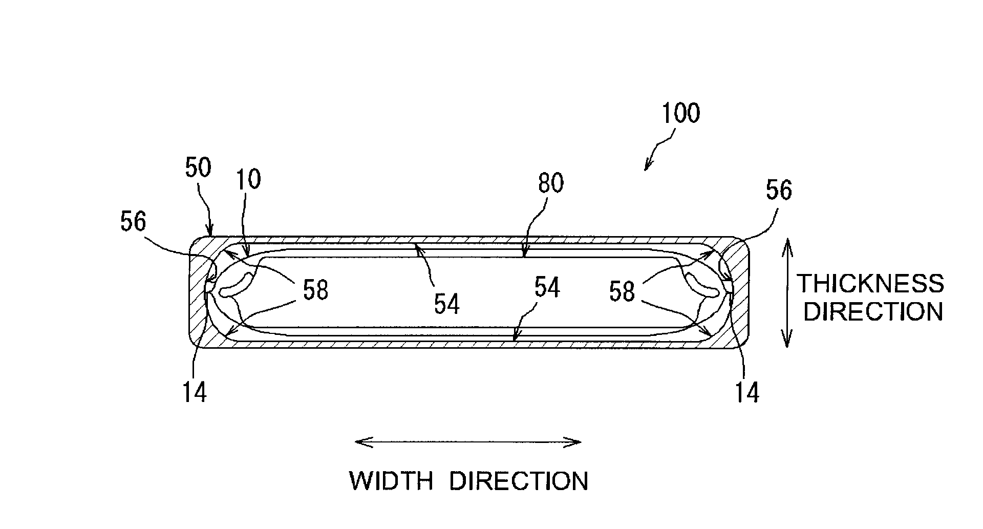
[0026]In the description of the present invention the term “battery” refers to an electrical storage device capable of providing desired electrical energy, and is not limited to a specific electrical storage mechanism (electrode assembly and electrolyte configuration). A secondary lithium battery such as a lithium-ion battery, a nickel-metal hydride secondary battery or other secondary battery, or a capacitor such as an electrical bilayer capacitor, etc. (i.e. a physical cell) are typical examples encompassed by the term battery herein.

[0027]In the present description the term “electrode assembly” refers to a structure comprising at least one positive electrode and negative electrode, and constituting the main body of a battery (electrical storage device).

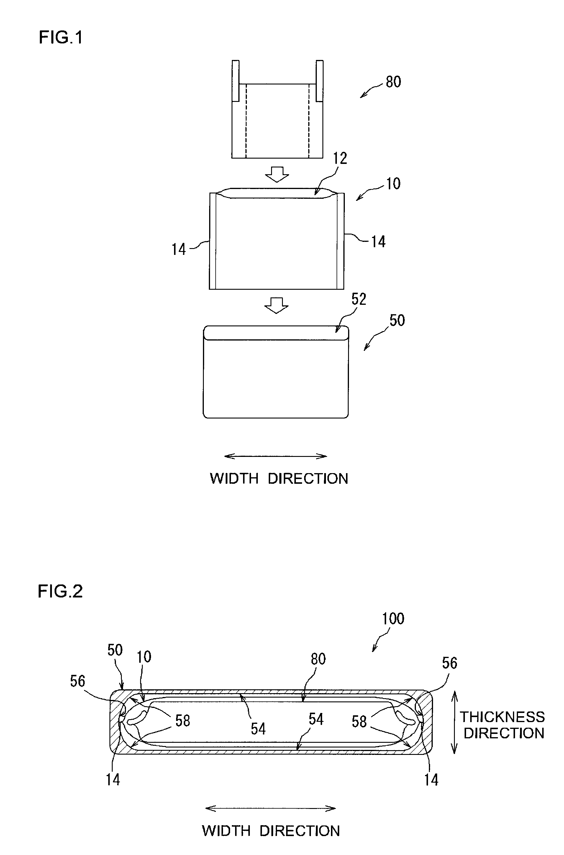
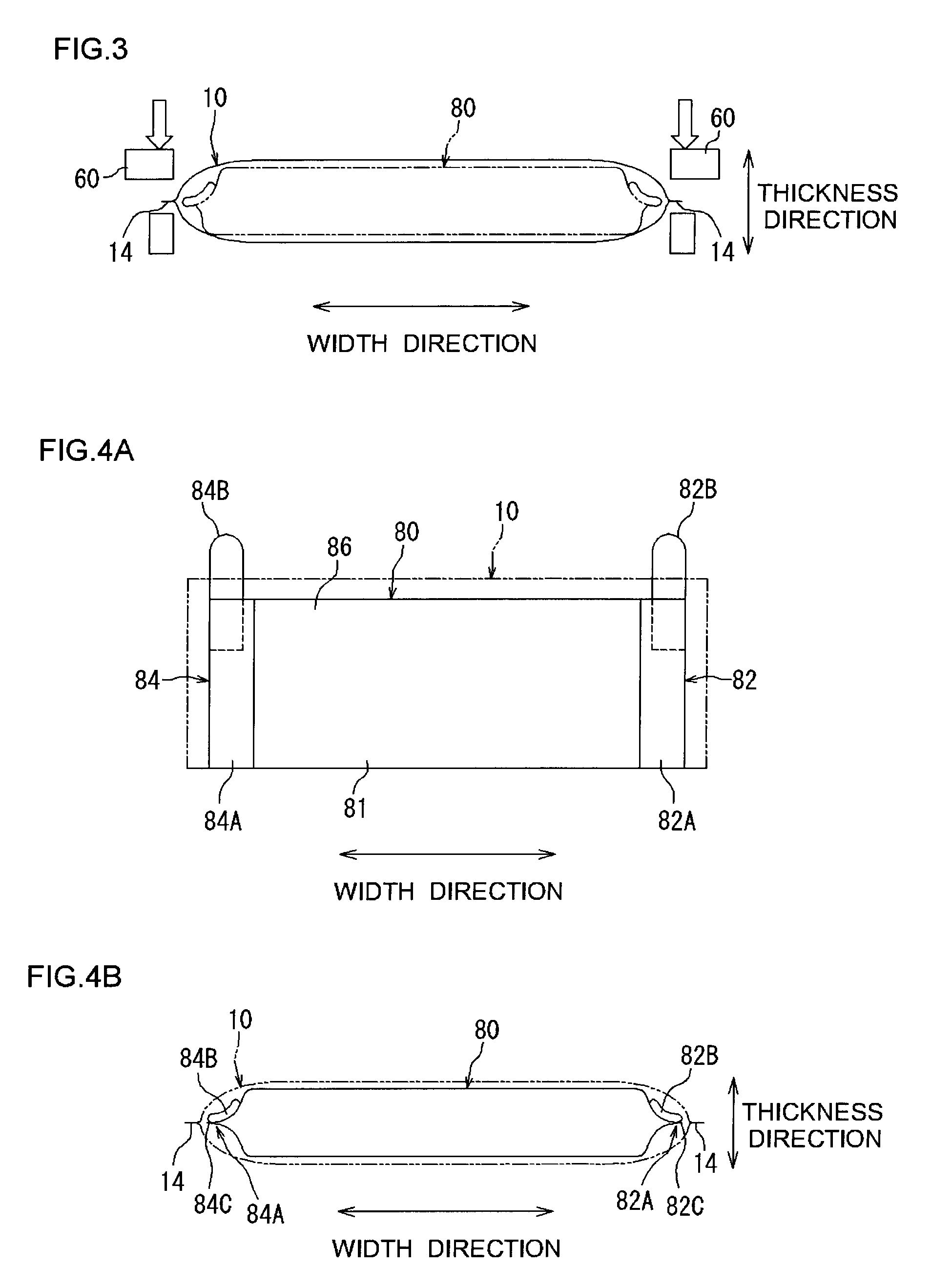
[0028]Embodiments of the present invention will be described below with reference to the drawings. In the drawings all positions and members providing the same action are described using the same symbols. The structure of the batte...


PUM

PropertyMeasurementUnit
thicknessaaaaaaaaaa
thickaaaaaaaaaa
thickaaaaaaaaaa

Abstract

A battery (100) includes an electrode body (80) having a positive electrode and a negative electrode and also includes an exterior case (50) formed in a box-like shape having an inner space corresponding to the electrode body (80). An insulation film (10) is provided between the electrode body (80) and the exterior case (50) to isolate them from each other. The insulation film (10) has a bag-like shape surrounding the electrode body (80) and is placed so as not to come into contact with corners (58) of the inner space.

Description

TECHNICAL FIELD[0001]The present invention relates to a battery comprising an electrode assembly and an exterior case formed into a box shape, and more particularly it relates to a battery structure suitable for mounting in a vehicle.[0002]This application is a national phase application of International Application No. PCT / JP2008 / 063137, filed Jul. 22, 2008, and claims priority based on Japanese Patent Application No. 2007-191446 filed Jul. 23, 2007, the contents of both of which are incorporated herein by reference.BACKGROUND ART[0003]Recently the importance of lithium-ion batteries, nickel-metal hydride batteries, and other secondary batteries as a power source not only for mounting in vehicles, but also for personal computers and other portable devices, has increased. In particular, lithium-ion batteries that are lightweight and provide a high energy density are expected to be used most suitably as high output power sources to be mounted in vehicles. In these types of batteries ...

Claims


Application Information

Patent Timeline
Patent Type & Authority Patents(United States)
IPC IPC(8): H01M6/10H01M2/00H01M50/119H01M50/417H01M50/474H01M50/477H01M50/486
CPCH01M2/0262H01M2/0277H01M2/028H01M2/14H01M10/052H01M10/058H01M2/0287H01M2/1653Y02E60/122Y02T10/7011H01M50/124H01M50/477H01M50/474H01M50/417H01M50/486H01M50/119Y02E60/10Y02P70/50H01M10/0587H01G11/52H01M10/345H01M2220/20H01M50/59H01M50/463H01M50/102Y02E60/13Y02T10/70
Inventor KAWASE, SATOMIMATSUURA, TOMOHIROYUGAHARA, KAORU
Owner TOYOTA JIDOSHA KK
Why Eureka
Try Eureka