Method and device for winding metal strip material

a metal strip and coiling technology, applied in forging/pressing/hammering machines, shaping tools, forging/hammering/pressing apparatuses, etc., can solve the problems of corresponding hysteria, difficulty in non-reproducibility of friction, and inability to systematic and precise force setting

Inactive Publication Date: 2013-09-03
SMS DEMAG AG
View PDF17 Cites 8 Cited by
  • Summary
  • Abstract
  • Description
  • Claims
  • Application Information

AI Technical Summary

Benefits of technology

[0036]The coiler mandrel of the invention makes it possible to dispense with a relatively large expa

Problems solved by technology

Of course, in a coiler mandrel according to the prior art described above, no systematic and precise force setting can be made.
The reason for this is the oblique planes, which, as a result of their high and nonreproducible friction, bring about a corresponding hysteresis.
The difficulty of the nonreproducibility of the friction is based on the presence of wear on the pressure member, on the segments and on the expanding bar.
The wear takes the form of removal of material, deformation, changes in surface roughness, etc.
A complicating factor is that the lubricating conditions can be unfavorable, since, for example, grease cannot emerge due to high pressure on the grease discharge borehole, or the grease burns or carbonizes when high temperatures develop.
The penetration of dirt and scale also has an unfavorable effect on the sliding surfaces if the dirt and sca

Method used


Image

  • Method and device for winding metal strip material
  • Method and device for winding metal strip material
  • Method and device for winding metal strip material

Examples


Embodiment Construction

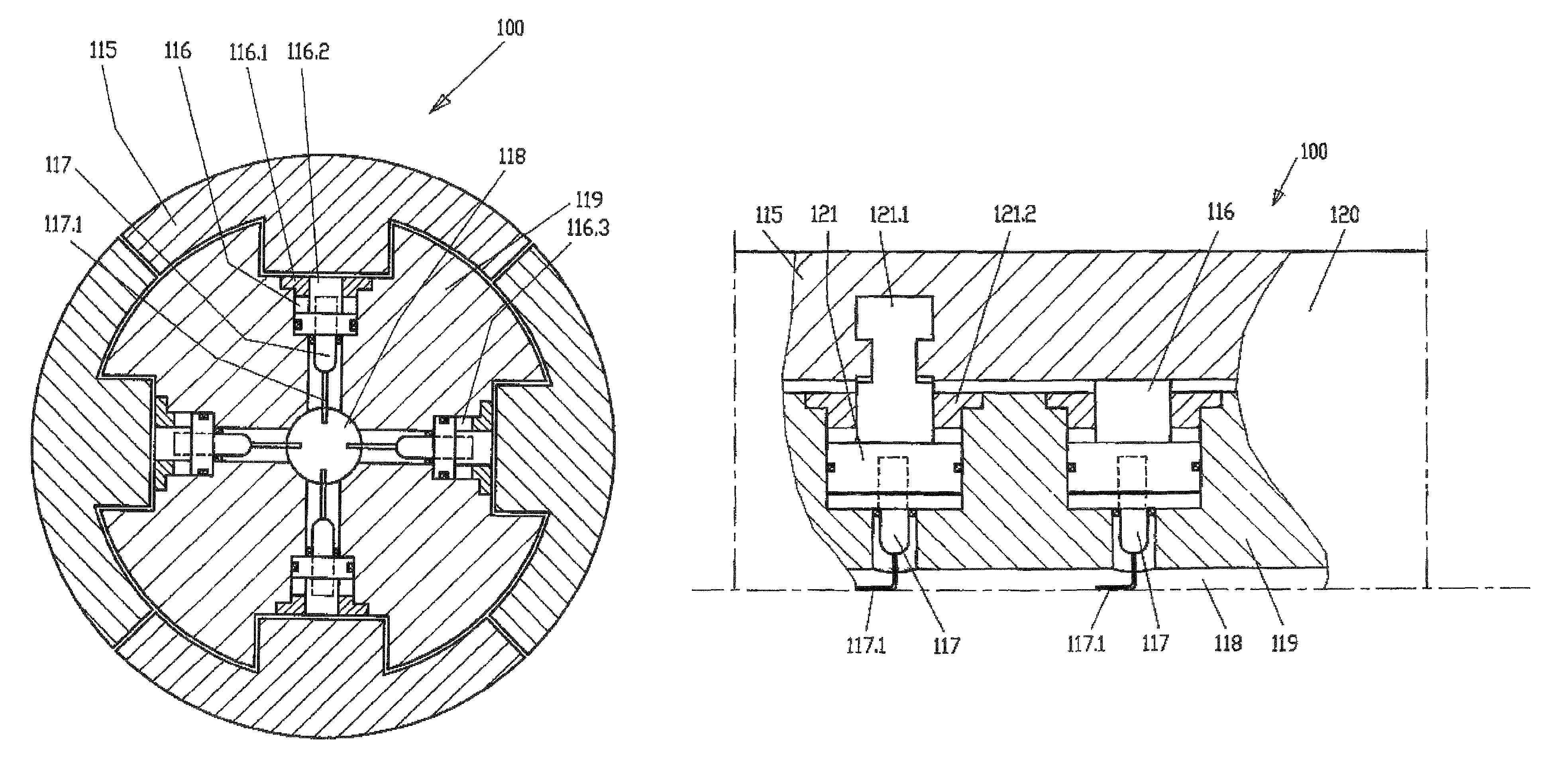
[0044]As shown in FIGS. 3 to 5, a coiler mandrel 100 of the invention is formed in the coiling section 120 with cylinders 116 and balancing cylinders 121. The cylinders 116 and balancing cylinders 121 move and / or hold the segments 115. The cylinders 116 and balancing cylinders 121 are operated, for example, hydraulically. Besides oil, other media, e.g., grease, can be used. The cylinders 116 are responsible for transmitting and / or producing the expansion force and the movement of the segments 115. As shown in the drawings, the cylinders 116 with their cylinder covers 116.1 and cylinder pistons 116.2 are set directly in the mandrel body 119. However, it is also conceivable for a complete cylinder 116 to be mounted as a unit in the coiler mandrel 100. Preferably, each cylinder 116 is provided with a position sensor 117, so that the exact position of the cylinder piston 116.2 can be determined and controlled by open-loop or closed-loop control. The cables 117.1 of the position sensors ...


PUM

PropertyMeasurementUnit
Forceaaaaaaaaaa
Pressureaaaaaaaaaa
Currentaaaaaaaaaa

Abstract

The invention concerns a method and a coiler mandrel for coiling metal strip (110), wherein the coiler mandrel (100) comprises a mandrel body (120), a plurality of radially expandable segments (115) arranged around the mandrel body (120), and a plurality of hydraulic cylinders (116) by which the segments (115) can be moved in the radial direction. To be able to coil the metal strip with a circular coil eye even when the friction varies in the individual cylinders, the invention proposes that each cylinder (116) of the plurality of cylinders be individually controlled.

Description

[0001]The present application is a 371 of International application PCT / EP2009 / 004598 filed Jun. 25, 2009, which claims priority of DE 2008 030 145.0, filed Jun. 27, 2008, the priority of these applications is hereby claimed and these applications are incorporated herein by reference.BACKGROUND OF THE INVENTION[0002]The invention concerns a method for coiling metal strip with[0003]a coiler mandrel with a mandrel body,[0004]a plurality of radially expandable segments arranged around the mandrel body, and[0005]a plurality of hydraulic cylinders by which the segments can be moved in the radial direction.[0006]The invention also concerns a device for coiling metal strip.[0007]In rolling mills, metal strip is shaped into sheets or into wound coils to allow transport and further processing of the strip within the mill or at the customer's site. Metal coils are produced by radial coiling of straight metal strip in a coiling installation. The metal strip is a product of a hot strip mill or ...

Claims


Application Information

Patent Timeline
IPC IPC(8): B65H18/10B65H75/24
CPCB21C47/30B21C47/02B65H75/242Y10T279/1024B65H75/249B65H75/24B65H18/02
Inventor KIPPING, MATTHIASFRANZ, ROLF
Owner SMS DEMAG AG
Why Eureka
Try Eureka