On demand non-rigid underwater oil and gas containment and retrieval system and method

a non-rigid, containment and retrieval technology, applied in the direction of water cleaning, wellbore/well accessories, construction, etc., can solve the problems of large environmental damage, inability of human beings inability to reach the depths to fix a broken well, so as to prevent the damage to the environment from the leakage

Active Publication Date: 2013-09-03
WATSON SR MICHAEL RAY
View PDF20 Cites 20 Cited by
  • Summary
  • Abstract
  • Description
  • Claims
  • Application Information

AI Technical Summary

Benefits of technology

[0020]It is another object of this invention to provide a system for connecting the discharge vent tube (2) to the top of the containment and retrieval system dome to provide a means for the discharged gas and oil (11) to be directed to the surface for harvesting and to prevent damage to the environment from the leak.
[0021]It is another object of this invention to provide a means to provide some rigidity to the discharge vent tube (2) after deployment through the use of air chambers (14) inflated by gases so that the discharge vent tube (2) retains its shape while in use.
[0022]It is another object of this invention to provide an underwater oil and gas retrieval system that can be activated remotely from the surface on a moment's notice when a catastrophic leak occurs without the necessity of first moving the device or other equipment.

Problems solved by technology

In May 2010 there was a disastrous deepwater oil well failure in the Gulf of Mexico that caused great damage to the environment because of the sheer volume of discharged oil that could not be contained for several months.
Because deep water oil and gas wells are submerged under water, often below 500 feet, the water pressure is so great that human beings cannot reach the depths to fix a broken well.
Each deepwater oil well is a disaster waiting to happen, even if the well is no longer in service.
One common problem with these systems is that the recovery systems are not stored at the well site or in position at the well before the oil well failure.
Therefore, there is a significant amount of time required to install at the well site any one of these systems in order to start containing and retrieving discharged oil.
Unfortunately, based on the discharge rates possible by broken oil wells, millions of gallons of polluting oil can have already been discharged before any of these systems could be realistically put in operating position.
There is no provision for storing this device permanently surrounding the oil well site on the bottom of the ocean for instant deployment.
Although the device could be stored nearby, its design would not allow it to be stored surrounding the well in place and it would need to be moved into place when needed.

Method used


Image

  • On demand non-rigid underwater oil and gas containment and retrieval system and method
  • On demand non-rigid underwater oil and gas containment and retrieval system and method
  • On demand non-rigid underwater oil and gas containment and retrieval system and method

Examples


Embodiment Construction

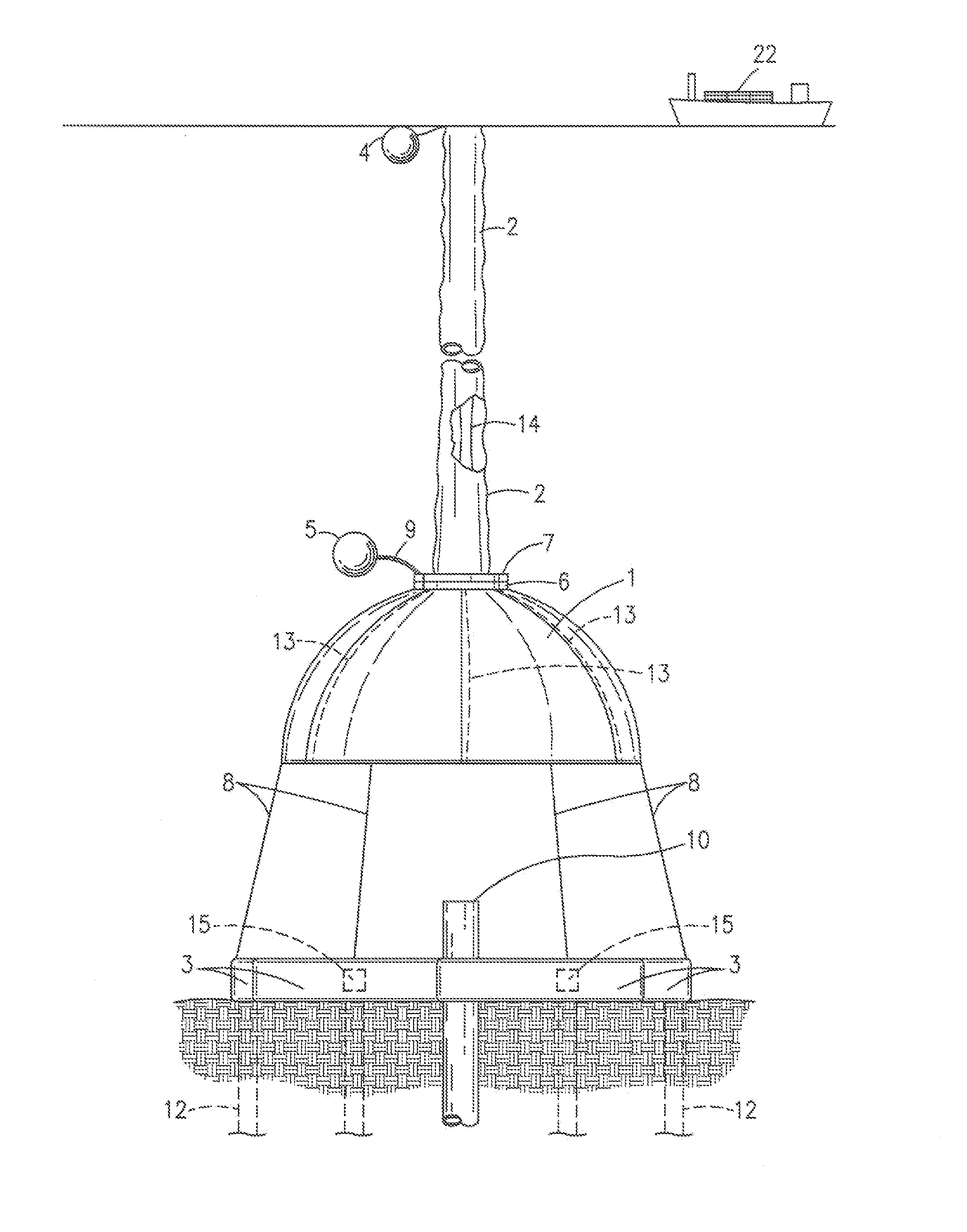
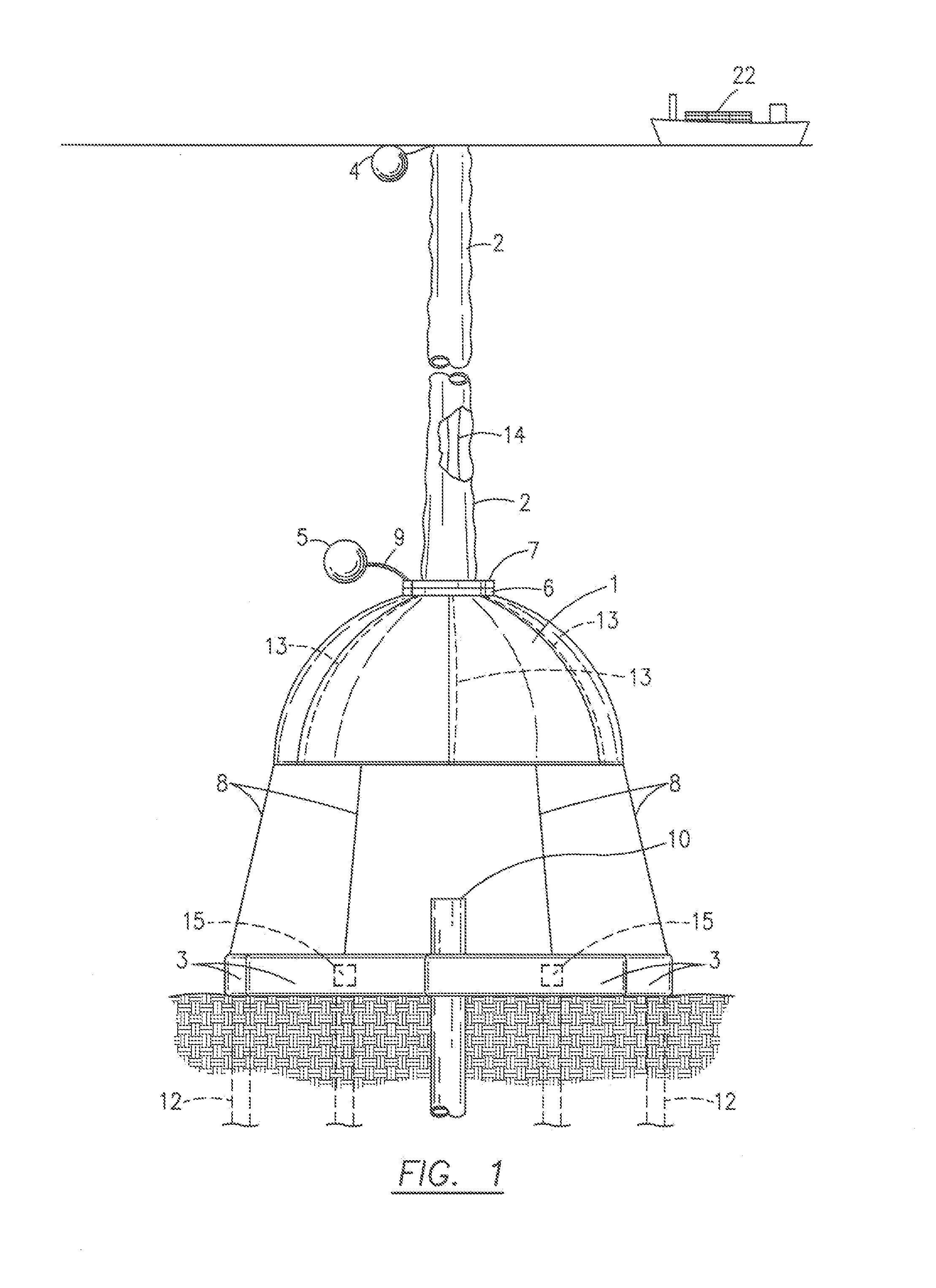
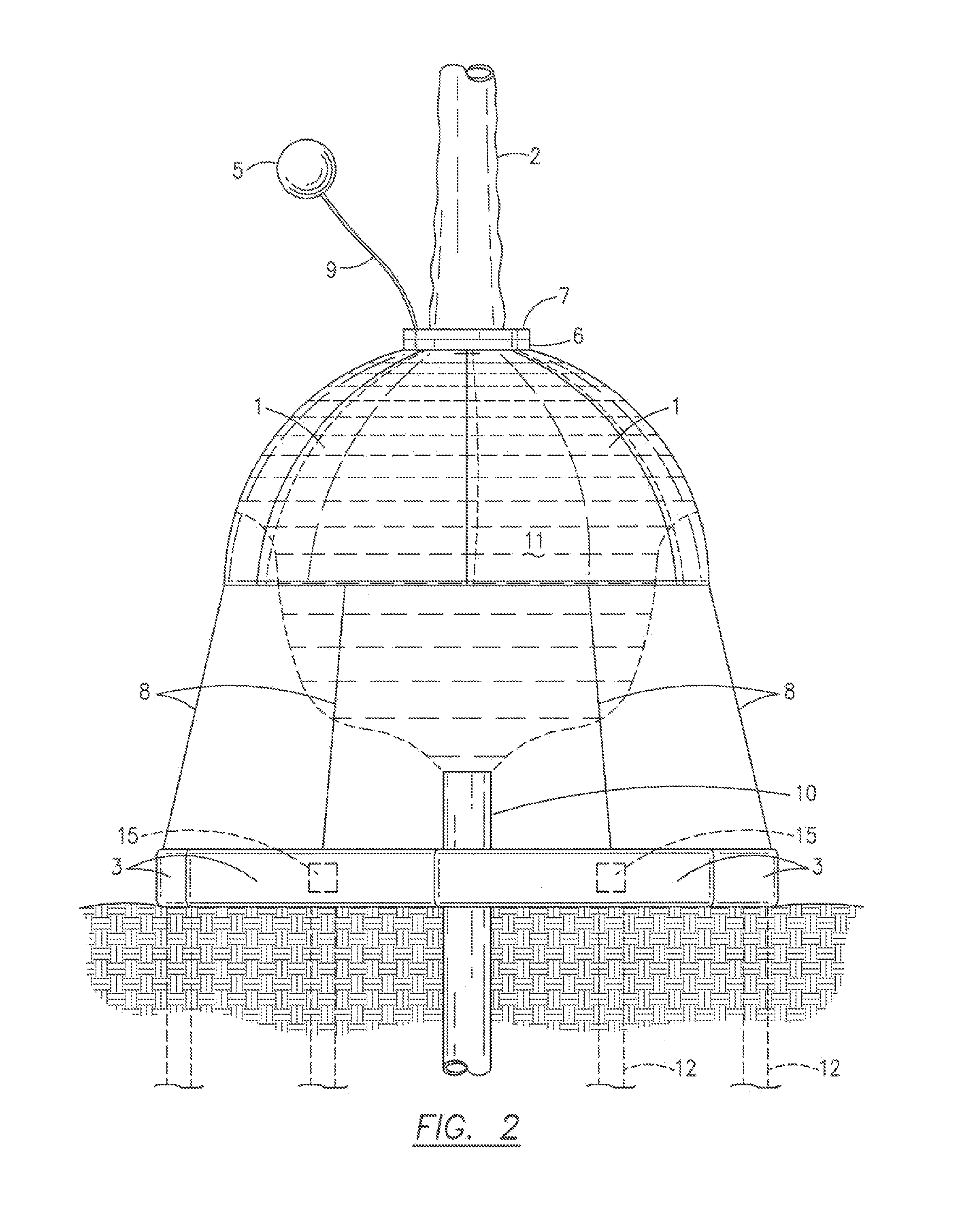
[0032]FIG. 1, FIG. 2, and FIG. 3 show the containment and retrieval system deployed in order to capture oil and gas (11) that is being discharged from disabled well shaft (10). In order to deploy the system, a RF signal is first sent from the surface recovery vessel or rig (22) to the discharge vent tube storage container (16) (FIG. 6) to open the container (16) followed by a RF signal to the discharge vent tube float (4) to release gases to inflate the discharge vent tube float (4) so that the float (4) rises to the surface bringing the discharge vent tube (2) and top with the float (4). A third RF signal is sent to the gas container cartridges (21) (FIG. 7A) in the air chambers (14) to inflate the air chambers in the discharge vent tube (2) to provide some rigidity and shape for the discharge vent tube (2). Next a RF signal is sent to activate the discharge vent tube cable winches and reels (19) to draw the dome ring (6) up tight against the discharge vent tube bottom ring (7) (FI...


PUM


Abstract

An underwater oil and gas containment and retrieval system comprising a collapsible deployable oil and gas containment canopy including a dome comprised of several separately stored dome panels (1), a discharge vent tube (2) including inflatable air chambers (14) to provide some rigidity and shape, dome panel storage containers (3) for storing the dome panels (1) on the ocean floor, and a separate discharge vent tube storage container (16) for storing the discharge vent tube separately on the ocean floor. The system is especially useful for deep water wells below 500 feet deep.

Description

CROSS REFERENCE TO RELATED APPLICATIONS[0001]This application is a continuation-in-part of co-pending U.S. patent application Ser. No. 13 / 040,708, filed Mar. 4, 2011.BACKGROUND OF THE INVENTION[0002]1. Field of the Invention[0003]This invention relates to a system to contain and retrieve oil and gas from a deep water well that has developed uncontrollable discharge. Specifically, the invention describes a non-rigid containment and retrieval system stored surrounding the well on the ocean floor in such a manner that it does not interfere with drilling or production activities and that can be activated at the time of the well failure on demand for immediate protection of the environment from deep water discharged oil and gas.[0004]2. Description of the Prior Art[0005]In May 2010 there was a disastrous deepwater oil well failure in the Gulf of Mexico that caused great damage to the environment because of the sheer volume of discharged oil that could not be contained for several months....

Claims


Application Information

Patent Timeline
Patent Type & Authority Patents(United States)
IPC IPC(8): E02B15/04
CPCE21B43/0122E02B2015/005
Inventor WATSON, SR., MICHAEL RAY
Owner WATSON SR MICHAEL RAY
Why Eureka
Try Eureka