PWM controller and control method for a DC-DC voltage converter

a voltage converter and controller technology, applied in the direction of dc-dc conversion, power conversion systems, climate sustainability, etc., can solve the problems of large output ripple exceeding the specification of voltage converters, high component cost, and inability to control the voltage converter, etc., to achieve small output voltage ripple

Active Publication Date: 2013-09-03
RICHTEK TECH
View PDF8 Cites 10 Cited by
  • Summary
  • Abstract
  • Description
  • Claims
  • Application Information

AI Technical Summary

Benefits of technology

[0005]An object of the present invention is to provide a PWM controller and method for a DC-DC voltage converter to have a small output voltage ripple as well as loop stability.
[0006]Another object of the present invention is to provide a PWM controller and method not relying on additional external elements to realize a small output voltage ripple and loop stability.

Problems solved by technology

For a DC-DC voltage converter, an output capacitor having a smaller equivalent series resistance will result in a smaller ripple of the output voltage; however, if the ripple is too small, the loop stability will be impaired.
Conversely, an output capacitor having a greater equivalent series resistance contributes to increasing loop stability, and yet the resultant output ripple may be so large as to exceed the specification of the voltage converter.
While the above two approaches realize a small output voltage ripple and loop stability by using external elements, higher component costs will be needed.

Method used


Image

  • PWM controller and control method for a DC-DC voltage converter
  • PWM controller and control method for a DC-DC voltage converter
  • PWM controller and control method for a DC-DC voltage converter

Examples


second embodiment

[0023]In a second embodiment as shown in FIG. 4, the MOSFETs Q1 and Q2, the output inductor L, the output capacitor COUT, and the resistor voltage divider 1 are configured as in the circuit of FIG. 3, and the PWM controller 21 also includes a synchronous-signal generator 23 and a PWM comparator circuit 25, but has a slightly different configuration from its counterpart shown in FIG. 3. In the synchronous-signal generator 23, the second signal 51 is also generated by the first low-pass filter 3 by filtering out the high-frequency component of the phase-node voltage VP and thus synchronous and in phase with the inductor current IL and similar to a triangular wave, but is provided for the positive input of the error amplifier 5 whose negative input is the first reference voltage VREF1. Likewise, the error amplifier 5 multiplies the difference between the second signal S1 and the first reference voltage VREF1 by an appropriate multiplication factor to generate a first signal S22 which i...

third embodiment

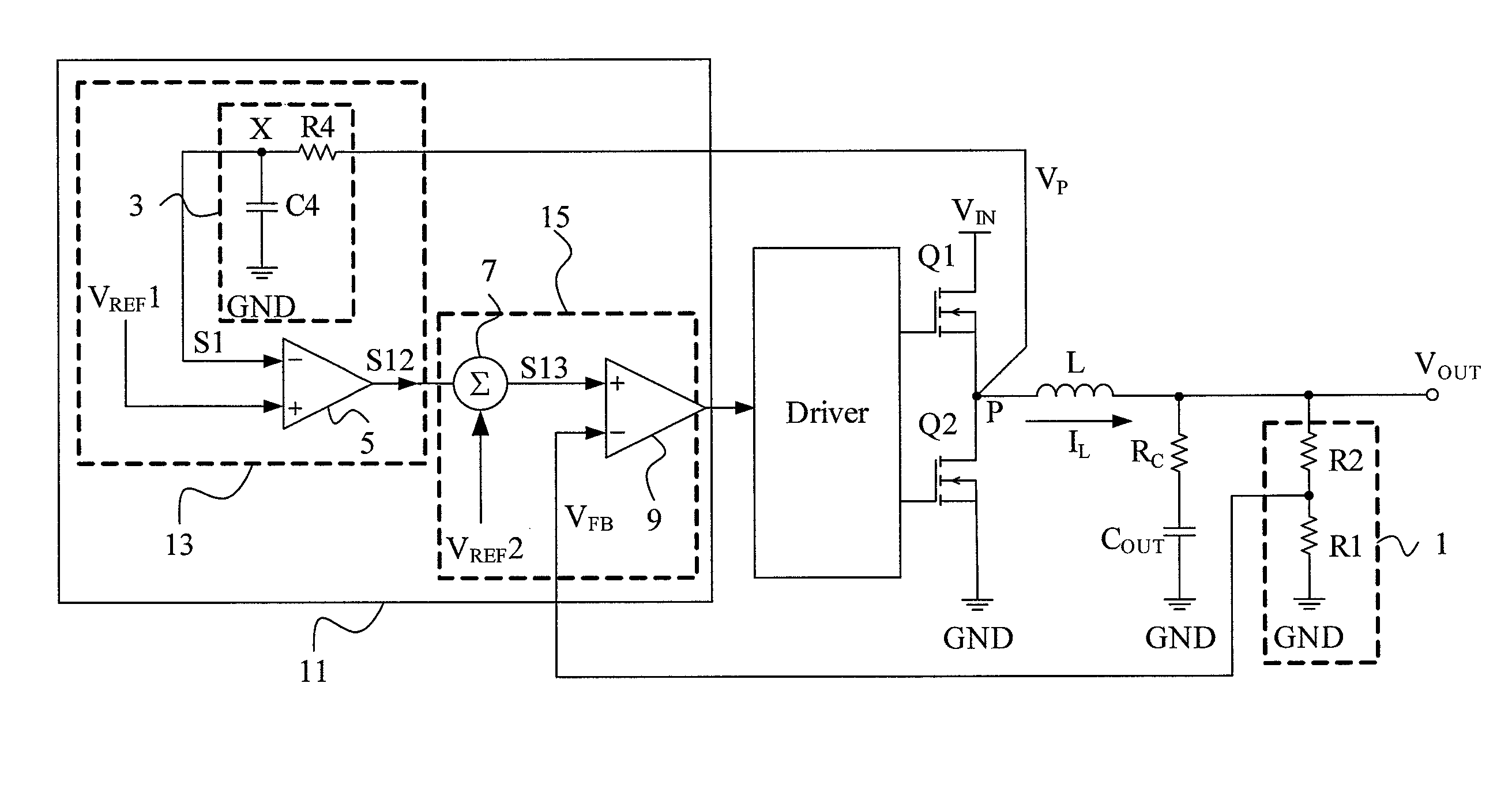
[0024]The third embodiment shown in FIG. 5 has a same configuration as that of FIG. 3, except that a synchronous-signal generator 33 is slightly different from its counterpart shown in FIG. 3. Likewise, the synchronous-signal generator 33 is in a PWM controller 31 including the PWM comparator circuit 15 and, however, includes a second low-pass filter 30 in addition to the first low-pass filter 3 and the error amplifier 5. The second low-pass filter 30 composed of a resistor R5 and a capacitor C5 filters out most of the AC component of the second signal S1 to generate a first reference voltage VREF1 which is similar to a DC voltage and represents the DC component of the output voltage VOUT. Therefore, the first signal S12 generated by the error amplifier 5 from the difference between the first reference voltage VREF1 and the second signal S1 is proportional to the slope of the inductor current IL and, in an IC package where no pins are provided for feedback of the output voltage VOUT...

fourth embodiment

[0025]The fourth embodiment shown in FIG. 6 has a same configuration as that of FIG. 4, except that a synchronous-signal generator 43 is slightly different from its counterpart shown in FIG. 4. Likewise, the synchronous-signal generator 43 is in a PWM controller 41 including the PWM comparator circuit 25 and, however, includes the second low-pass filter 30 in addition to the first low-pass filter 3 and the error amplifier 5, to filter out most of the AC component of the second signal S1 to generate the first reference voltage VREF1 similar to a DC voltage representing the DC component of the output voltage VOUT. This embodiment has the same advantages as those of the circuit shown in FIG. 5.


PUM


Abstract

A PWM controller and control method for a DC-DC voltage converter filter the high-frequency component of the voltage at the phase node between high-side and low-side elements of the voltage converter to generate a signal synchronous and in phase or out-of-phase with the inductor current of the voltage converter, to achieve a low-ripple output voltage and stable loop control.

Description

FIELD OF THE INVENTION[0001]The present invention is related generally to a DC-DC voltage converter and, more particularly, to a PWM controller and method for a DC-DC voltage converter.BACKGROUND OF THE INVENTION[0002]In conventional constant on-time or hysteretic mode self-clocking DC-DC voltage converters, the generation of the PWM signal is triggered by the ripple of the output voltage. For a DC-DC voltage converter, an output capacitor having a smaller equivalent series resistance will result in a smaller ripple of the output voltage; however, if the ripple is too small, the loop stability will be impaired. Conversely, an output capacitor having a greater equivalent series resistance contributes to increasing loop stability, and yet the resultant output ripple may be so large as to exceed the specification of the voltage converter. Hence, there is always a trade-off between a small output voltage ripple and enough loop stability.[0003]There have been two approaches to achieve a ...

Claims


Application Information

Patent Timeline
Patent Type & Authority Patents(United States)
IPC IPC(8): G05F1/575
CPCH02M1/14H02M3/1588Y02B70/1466Y02B70/10
Inventor WANG, KO-CHENGLIU, KUO-PINGTSENG, CHIH-WEI
Owner RICHTEK TECH
Why Eureka
Try Eureka