
Body-worn vital sign monitor

a vital sign and monitor technology, applied in the field of medical devices for monitoring vital signs, can solve the problems of difficult to effectively monitor patients in this way, heavy and unwieldy conventional vital sign monitors, and general illness of patients in these areas, so as to minimize the corruption of vital signs and improve the safety of hospitalized patients

Active Publication Date: 2013-09-03
SOTERA WIRELESS
View PDF459 Cites 114 Cited by
  • Summary
  • Abstract
  • Description
  • Claims
  • Application Information

AI Technical Summary

Benefits of technology

The body-worn monitor provides reliable, continuous vital sign monitoring with reduced false alarms and improved accuracy, suitable for ambulatory patients by accounting for motion and posture, ensuring timely alerts to medical professionals.

Problems solved by technology

Patients in these areas are generally sick and require a relatively high degree of medical attention.
It can be difficult to effectively monitor patients in this way, however, because they are often ambulatory and not constrained to a single hospital room.
This poses a problem for conventional vital sign monitors, which are typically heavy and unwieldy, as they are not intended for the ambulatory population.
Some companies have developed ambulatory vital sign monitors with limited capabilities (e.g. cuff-based blood pressure using oscillometry and SpO2 monitoring), but typically these devices only make intermittent, rather than continuous, measurements.
And even these measurements tend to work best on stationary patients, as they are easily corrupted by motion-related artifacts.

Method used


Image

  • Body-worn vital sign monitor
  • Body-worn vital sign monitor
  • Body-worn vital sign monitor

Examples


Embodiment Construction

System Overview

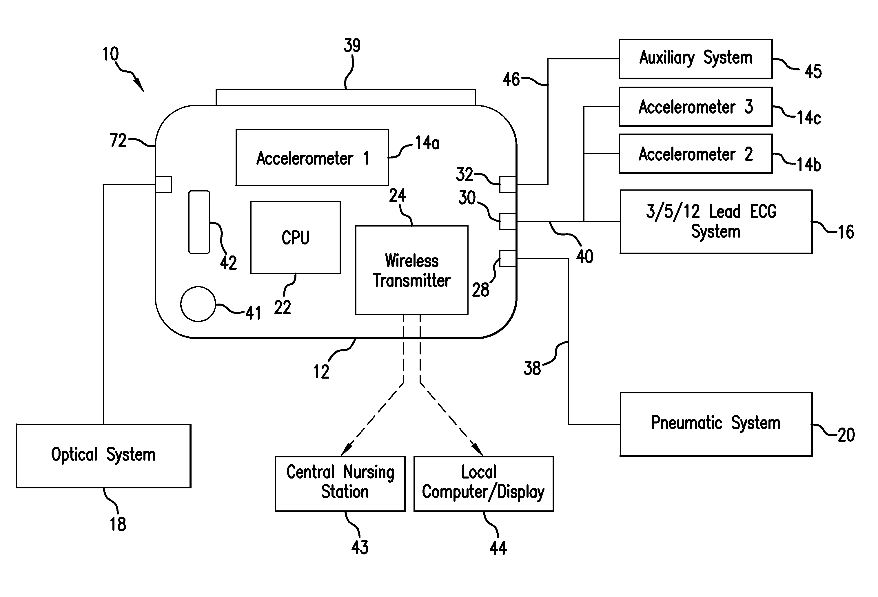
[0054]FIG. 1 shows a schematic drawing of a body-worn monitor 10 according to the invention featuring a wrist-worn transceiver 72 that continuously determines vital signs (e.g. blood pressure, SpO2, heart rate, respiratory rate, and temperature) and motion-related properties (e.g. posture, arm height, activity level, and degree of motion) for an ambulatory patient in a hospital. The monitor 10 is small, lightweight, and comfortably worn on the patient's body during their stay in the hospital; its form factor is described in detail below. A medical professional can apply the monitor, for example, to a recently admitted patient waiting in the ED, and the same monitor can provide continuous monitoring during their stay in the hospital. For example, the patient can wear the monitor in their hospital room, as they receive specific procedures or tests, during transport to other rooms, and even during surgery. The monitor 10 provides continuous monitoring, and features a sof...


PUM


Abstract

The invention provides a body-worn monitor featuring a processing system that receives a digital data stream from an ECG system. A cable houses the ECG system at one terminal end, and plugs into the processing system, which is worn on the patient's wrist like a conventional wristwatch. The ECG system features: i) a connecting portion connected to multiple electrodes worn by the patient; ii) a differential amplifier that receives electrical signals from each electrode and process them to generate an analog ECG waveform; iii) an analog-to-digital converter that converts the analog ECG waveform into a digital ECG waveform; and iv) a transceiver that transmits a digital data stream representing the digital ECG waveform (or information calculated from the waveform) through the cable and to the processing system. Different ECG systems, typically featuring three, five, or twelve electrodes, can be interchanged with one another.

Description

CROSS REFERENCES TO RELATED APPLICATIONS[0001]Not ApplicableSTATEMENT REGARDING FEDERALLY SPONSORED RESEARCH OR DEVELOPMENT[0002]Not ApplicableBACKGROUND OF THE INVENTION[0003]1. Field of the Invention[0004]The present invention relates to medical devices for monitoring vital signs, e.g., arterial blood pressure.[0005]2. Description of the Related Art[0006]Conventional vital sign monitors are used throughout the hospital, and are particularly commonplace in high-acuity areas such as the intensive care unit (ICU), emergency department (ED), or operating room (OR). Patients in these areas are generally sick and require a relatively high degree of medical attention. The ratio between medical professionals and patient in these areas is typically high compared to lower-acuity areas of the hospital. Even in such areas, however, it is still common practice for medical professionals to measure vital signs such as blood pressure, respiratory rate, oxygen saturation (SpO2), heart rate, and te...

Claims


Application Information

Patent Timeline
Patent Type & Authority Patents(United States)
IPC IPC(8): A61B5/04
CPCA61B5/0002A61B5/0006A61B5/0205A61B5/02125A61B5/02141A61B5/02225A61B5/1116A61B5/681A61B5/7435A61B5/743A61B5/6824A61B2560/0276A61B5/6823A61B5/6826A61B2560/0209A61B2562/043
Inventor MOON, JIMVISSER, HENKHUNT, ROBERT
Owner SOTERA WIRELESS
Learn More