
Sensor control apparatus

a sensor control and sensor technology, applied in the direction of electrical control, machines/engines, instruments, etc., can solve the problems of variability in the accuracy of detecting oxygen concentration among individual oxygen sensors, and achieve the effect of satisfying the detection accuracy of oxygen sensors

Active Publication Date: 2013-09-03
NGK SPARK PLUG CO LTD
View PDF6 Cites 0 Cited by
  • Summary
  • Abstract
  • Description
  • Claims
  • Application Information

AI Technical Summary

Benefits of technology

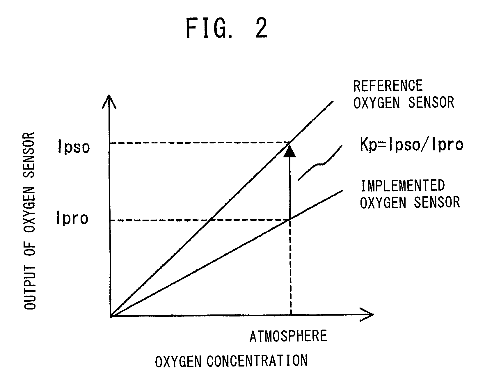
The present invention provides a method for accurately calibrating the output of an oxygen sensor in an internal combustion engine. This is achieved by calculating the average output value of the oxygen sensor during a fuel cut operation and using it to create a correction coefficient. This resultant correction coefficient allows for the accurate calibration of the oxygen sensor output in relation to oxygen concentration, leading to better detection accuracy for a long period of time.

Problems solved by technology

However, there has been a problem in that accuracy in detecting oxygen concentration varies among individual oxygen sensors because of variation in output characteristic among the individual oxygen sensors and deterioration of each oxygen sensor with time.

Method used


Image

  • Sensor control apparatus
  • Sensor control apparatus
  • Sensor control apparatus

Examples


Embodiment Construction

[0030]An embodiment of the present invention will now be described.

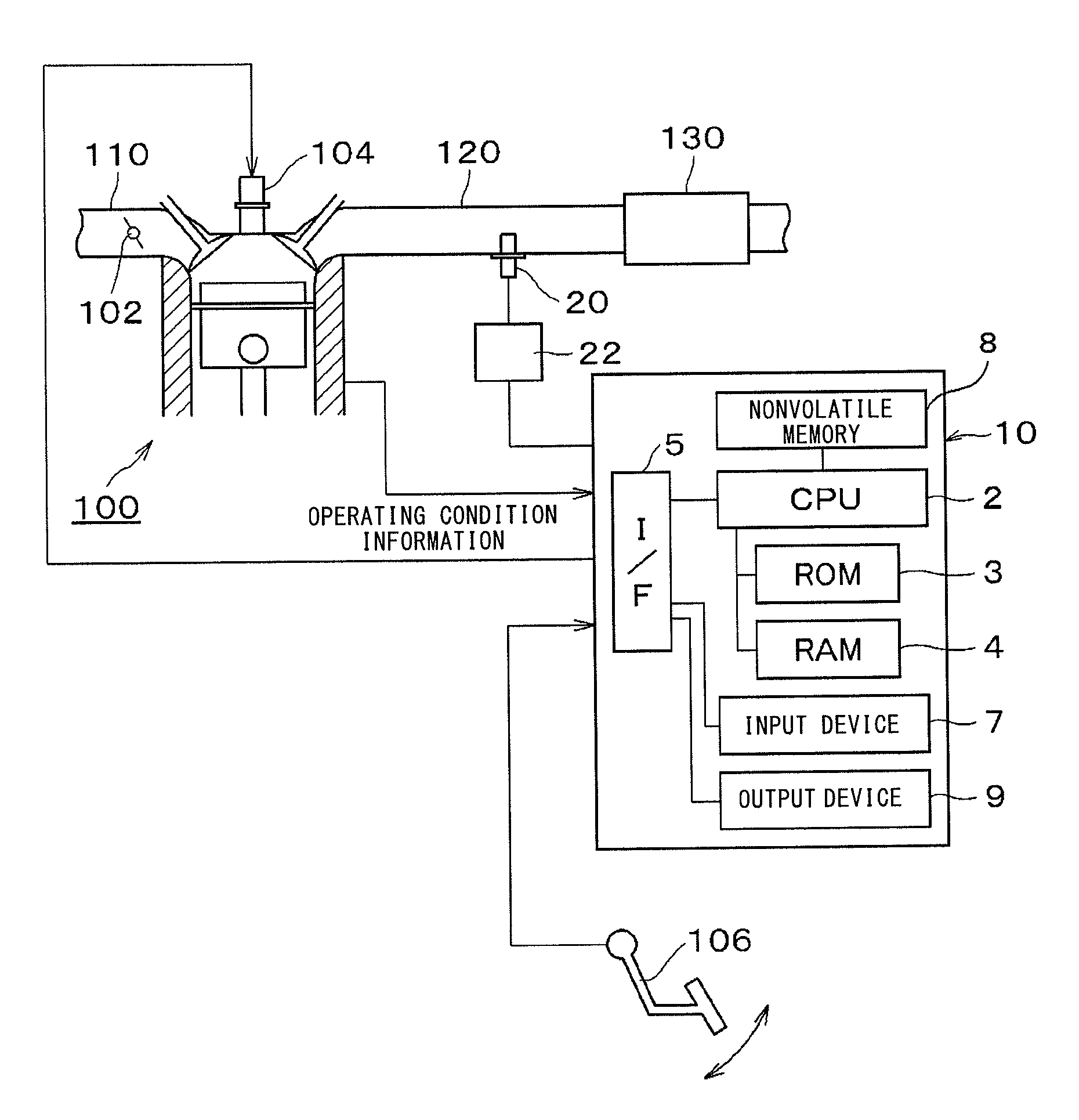
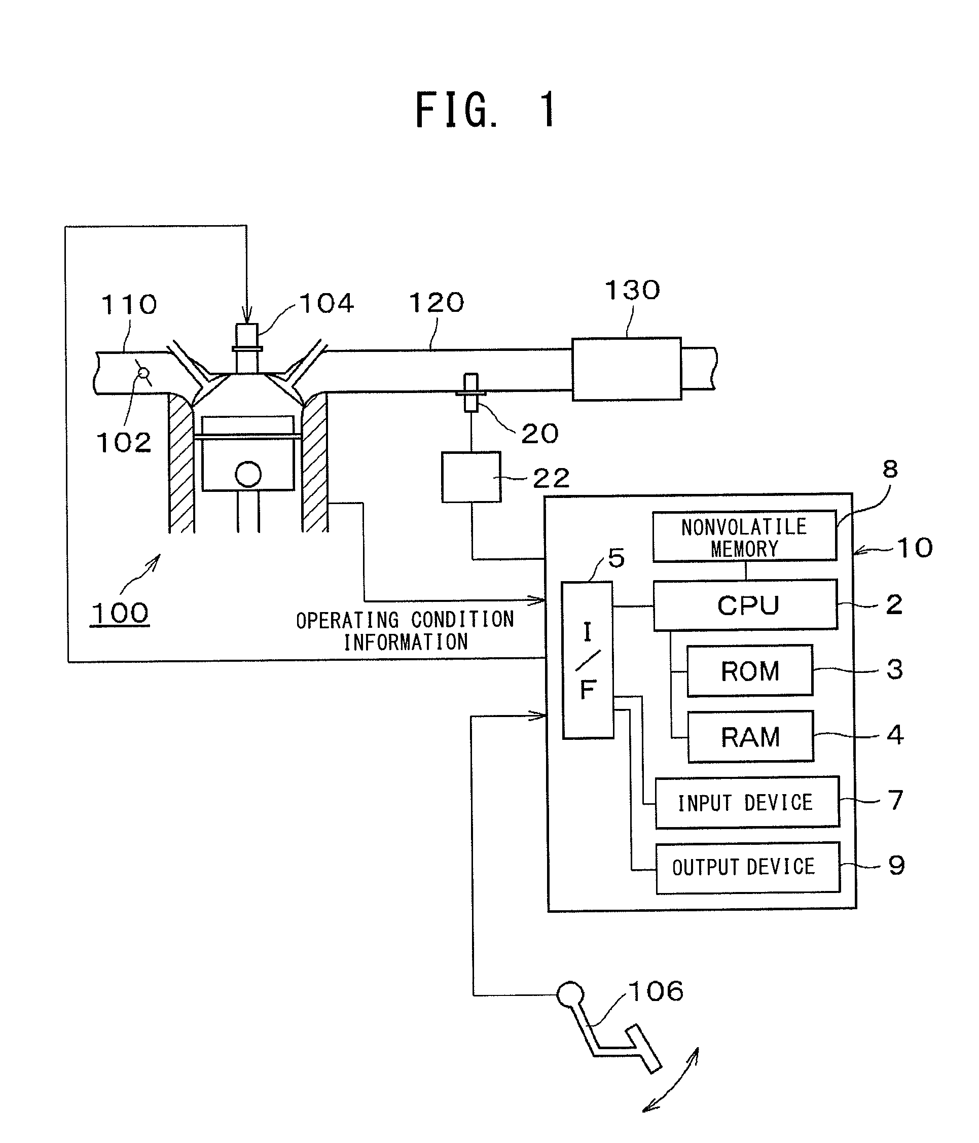
[0031]FIG. 1 is a diagram showing the overall configuration of a system including an oxygen sensor control apparatus 10 according to an embodiment of the present invention. An oxygen sensor (hereinafter may be referred to as an “implemented oxygen sensor”) 20 is attached to an exhaust pipe 120 of an internal combustion engine 100 of a vehicle, and a controller 22 is connected to the implemented oxygen sensor 20. An oxygen sensor control apparatus (ECU; engine control unit) 10 is connected to the controller 22.

[0032]A throttle valve 102 is provided in an intake pipe 110 of the engine 100, and an injector 104 for supplying fuel into a cylinder is provided for each cylinder of the engine 100. Furthermore, an exhaust gas purification catalyst 130 is attached to a downstream side of the exhaust pipe 120. Moreover, various unillustrated sensors (a pressure sensor, a temperature sensor, a crank angle sensor, etc.) are provi...


PUM


Abstract

An oxygen sensor control apparatus (10) obtains a correction coefficient for calibrating the relation between oxygen concentration and an output value of an oxygen sensor (20), when a fuel cut operation of an internal combustion engine (100) is performed. The apparatus includes average output value calculation means; inter-fuel-cut average output value calculation means; and correction coefficient calculation means.

Description

TECHNICAL FIELD[0001]The present invention relates to an oxygen sensor control apparatus which calibrates the relation between oxygen concentration of exhaust gas discharged from an internal combustion engine and output of an oxygen sensor for detecting the oxygen concentration, and which detects the oxygen concentration of the exhaust gas.BACKGROUND ART[0002]Conventionally, an oxygen sensor has been disposed in an exhaust passage (exhaust pipe) of an internal combustion engine of an automobile or the like so as to detect the oxygen concentration of exhaust gas, on the basis of which the air-fuel ratio is controlled. An example of such an oxygen sensor is one which includes a gas detection element having at least one cell in which a pair of electrodes are formed on oxygen-ion conductive zirconia. However, there has been a problem in that accuracy in detecting oxygen concentration varies among individual oxygen sensors because of variation in output characteristic among the individua...

Claims


Application Information

Patent Timeline
Patent Type & Authority Patents(United States)
IPC IPC(8): G01C25/00
CPCF02D41/123F02D41/2441F02D41/2454F02D41/2474F02D41/1454
Inventor ISHIGURO, YASUHIROYAZAWA, KATSUNORIINAGAKI, HIROSHISUZUKI, KEIJISHIMOZATO, TETSUMA
Owner NGK SPARK PLUG CO LTD
Learn More