
Hand-held power tool

a hand-held power tool and power switch technology, applied in the can solve the problems of reducing affecting the ergonomics and comparatively large construction height, and achieve the effect of simple design measures and optimal illumination of the working field of hand-held power tools

Inactive Publication Date: 2013-09-10
ROBERT BOSCH GMBH
View PDF10 Cites 11 Cited by
  • Summary
  • Abstract
  • Description
  • Claims
  • Application Information

AI Technical Summary

Benefits of technology

[0004]An object of the present invention is to illuminate the working field of a hand-held power tool optimally without limiting ergonomics, using simple design measures.
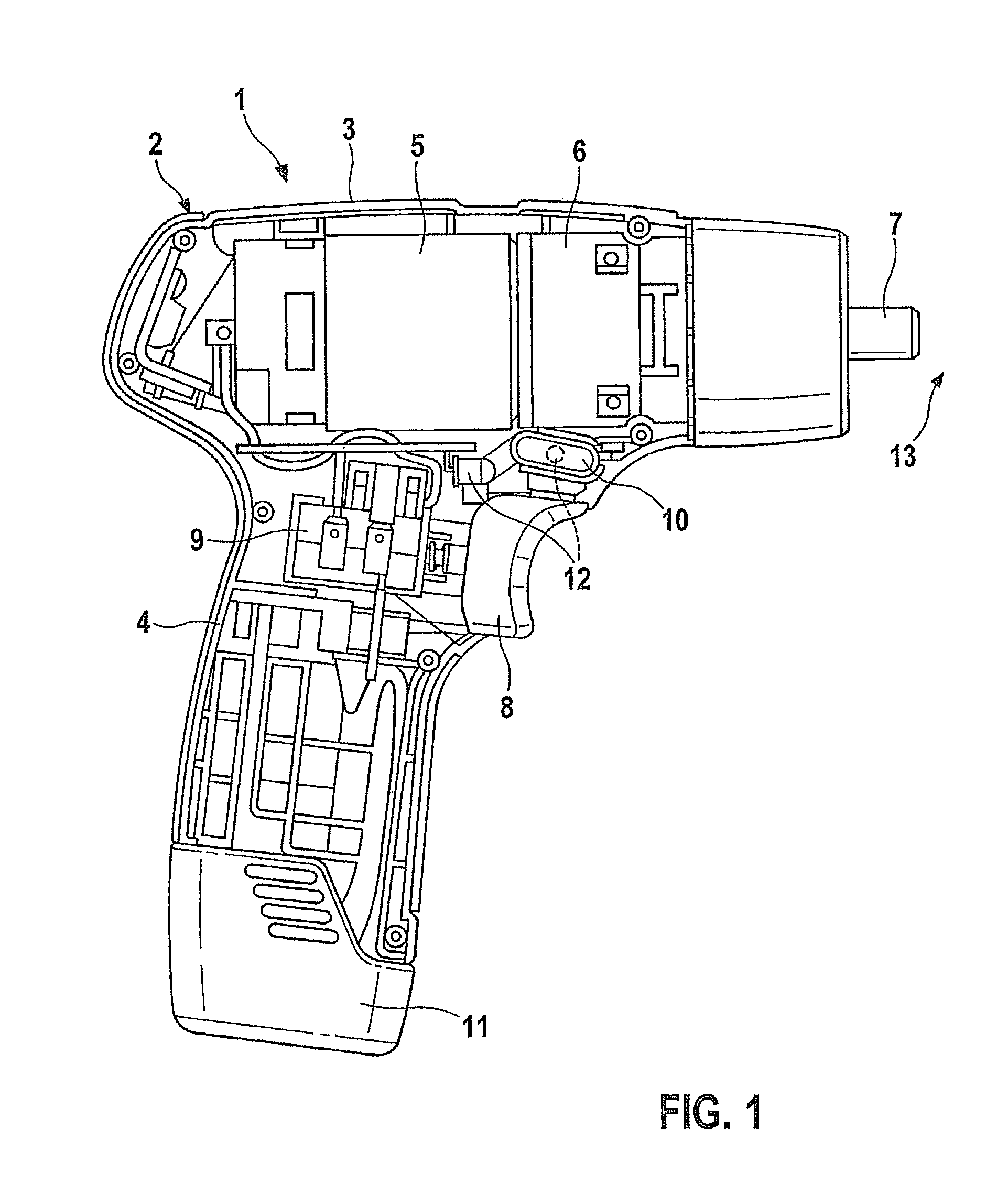
[0006]This embodiment has various advantages. Since the trigger switch is a component of the illuminating element, the light source may be situated in the immediate proximity of the switch, so that it is no longer necessary to position the light source at a greater distance from the switch for ergonomic reasons. On the one hand, there are more design options for situating and positioning the light source in the housing. On the other hand, it is possible to design the light source to be small, since comparatively close positioning to the working field and thus the use of relatively low light intensities is possible. Moreover, the construction height of the light source is reduced, since it is possible to situate the light source at only a slight angle to the tool axis of the held-held power tool or parallel to the axis; the trigger switch, which is in the beam path of the light beam that is emitted by the light source, provides for distributing or reflecting the light beams in the direction of the working field to be illuminated.
[0007]According to one advantageous embodiment, the light source is situated outside the trigger switch in the housing, and the light beams of the light source are directed at the trigger switch, which has an optical forwarding function for the light beams that strike it. This may be implemented for example by the trigger switch being made at least partially of a transparent material, so that the light beams emitted by the light source pass through the switch in the direction of the working field to be illuminated. In this way a bundled light beam that strikes the switch may be focused in the manner of a lens, deflected, or possibly even fanned out, in order to achieve a desired illumination effect. Furthermore, it is also possible to let the light beam striking the switch reflect on the surface of the switch, for example by providing the switch with a mirror-coated surface or a polished surface which enables reflection. Finally, the geometry of the switch may also be prepared for a desired optical effect, for example in that the switch has a curved contour for bundling or scattering light; here the geometry of the switch may be designed appropriately, both in the case of a transparent material through which the light passes and in the case of a reflection on the surface. Furthermore, this embodiment is robust, since the light source within the switch is protected from soiling and damage.
[0008]According to another preferred embodiment, the light source is integrated into the interior of the trigger switch. This design is particularly space-saving, since no additional installation space needs to be reserved for the light source. Either an opening is made in the trigger switch for the emergence of the light beams that are emitted by the light source, or the wall of the trigger switch, designed as a hollow body, is made of a transparent material through which the light beams pass.

Problems solved by technology

A disadvantage here is the comparatively large construction height, which comes about due to the angular positioning of the lighting element relative to the tool axis.
The trigger switch for activating the electric drive motor, positioned in the area of transition between the motor housing and the grip housing, cannot be operated in an optimal, ergonomic manner because of the lighting element being situated directly in front.

Method used


Image

  • Hand-held power tool
  • Hand-held power tool
  • Hand-held power tool

Examples


Embodiment Construction

[0014]In the figures, identical components are given identical reference numerals.

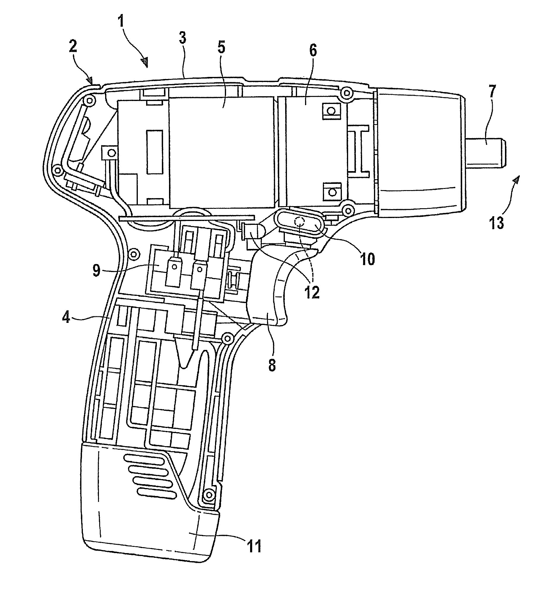
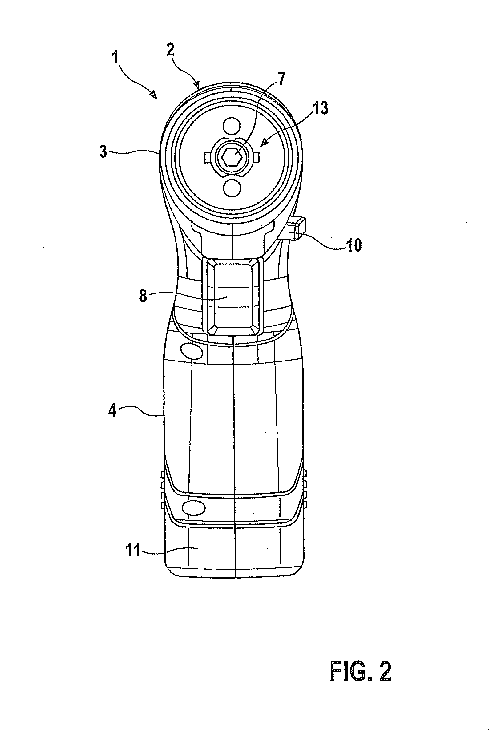
[0015]Hand-held power tool 1 shown in FIG. 1 has a housing 2, made up of a motor housing 3 and a grip housing 4 oriented approximately perpendicularly to motor housing 3, motor housing 3 and grip housing 4 possibly being designed as a single piece or as separate components. Contained in motor housing 3 is an electric drive motor 5 and also a gear unit 6, which is actuated by drive motor 5 and through which the drive motion is transferred to a spindle or tool-holding fixture 7 for receiving a tool. Gear unit 6 is, for example, a planetary transmission for converting the high motor speed to the lower speed of the tool-holding fixture.

[0016]Drive motor 5 is put into operation via a trigger switch 8, which is movable relative to the housing, and is located on grip housing 4, the speed of rotation of the drive motor being adjusted via the measure of actuation of trigger switch 8, which acts internally on a ...


PUM


Abstract

A hand-held power tool is equipped with a lighting element for illuminating the working field, the lighting element including a light source and a trigger switch for activating or adjusting a drive motor forming a component of the lighting element in such a way that light beams emitted by the light source are guided via the trigger switch to the working field.

Description

FIELD OF THE INVENTION[0001]The present invention relates to a hand-held power tool, in particular an electrically operated hand-held power tool such as a rechargeable screwdriver or rechargeable drill.BACKGROUND INFORMATION[0002]U.S. Pat. No. 7,185,998 B2 describes a rechargeable screwdriver or drill, which has an electric drive motor for driving a tool-holding fixture in a motor housing. Extending approximately perpendicularly to the motor housing is a grip housing, at the lower end of which a rechargeable battery pack for supplying power is situated. Situated in the area of transition between the rechargeable battery pack and the grip housing is a lighting element, which includes a light source having a lens placed in front of it, through which a light beam is emitted to the working field lying directly in front of the tool-holding fixture. Because of the comparatively large distance between the lighting element and the working field, the lighting element must have relatively hig...

Claims


Application Information

Patent Timeline
Patent Type & Authority Patents(United States)
IPC IPC(8): B25B23/18
CPCB25F5/021B25B23/18
Inventor ROEHM, HEIKO
Owner ROBERT BOSCH GMBH
Learn More