Electromagnetically shielded enclosure and entry seal

a technology of electromagnetic shielding and enclosure, applied in magnetic/electric field screening, instruments, parkings, etc., can solve the problems of unwanted detection, insufficient shielding effectiveness, and increased risk of unwanted detection

Active Publication Date: 2013-09-10
SELECT FABTORS
View PDF15 Cites 29 Cited by
  • Summary
  • Abstract
  • Description
  • Claims
  • Application Information

AI Technical Summary

Problems solved by technology

In addition, testing of electronic equipment often requires a similar electromagnetically “quiet” environment.
Such situations include, for example, the use of computer and military electronics where there is the risk of unwanted detection of a radiated radiofrequency signal or unwanted detection of the associated harmonics and signature of r

Method used


Image

  • Electromagnetically shielded enclosure and entry seal
  • Electromagnetically shielded enclosure and entry seal
  • Electromagnetically shielded enclosure and entry seal

Examples


Embodiment Construction

[0023]There are various techniques for the design and construction of an electromagnetically shielded enclosure. The shape, size and materials selected for an electromagnetically shielded enclosure may vary based on the intended application. The present invention and the various embodiments depicted and envisioned herein do not rely on specific geometries, materials, or structural designs, but rather, the entry seal of the present invention may be adapted and modified to fit a wide range of electromagnetically shielded enclosures. Such adaptations and modifications will become evident to one skilled in the art after reading this specification and viewing the attached drawings.

[0024]For a general understanding of the present invention, reference is made to the drawings. In the drawings, like reference numerals have been used throughout to designate identical elements.

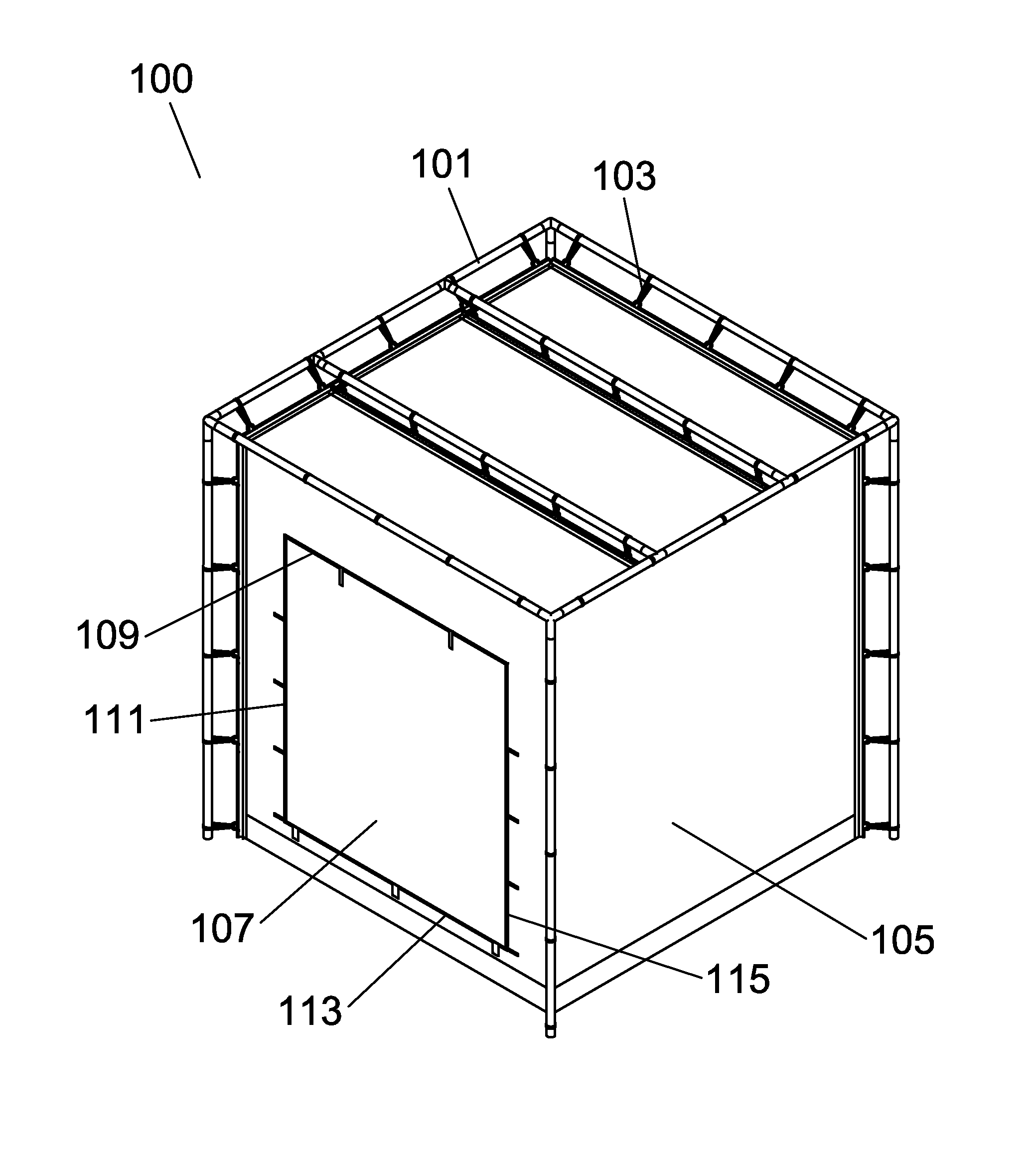
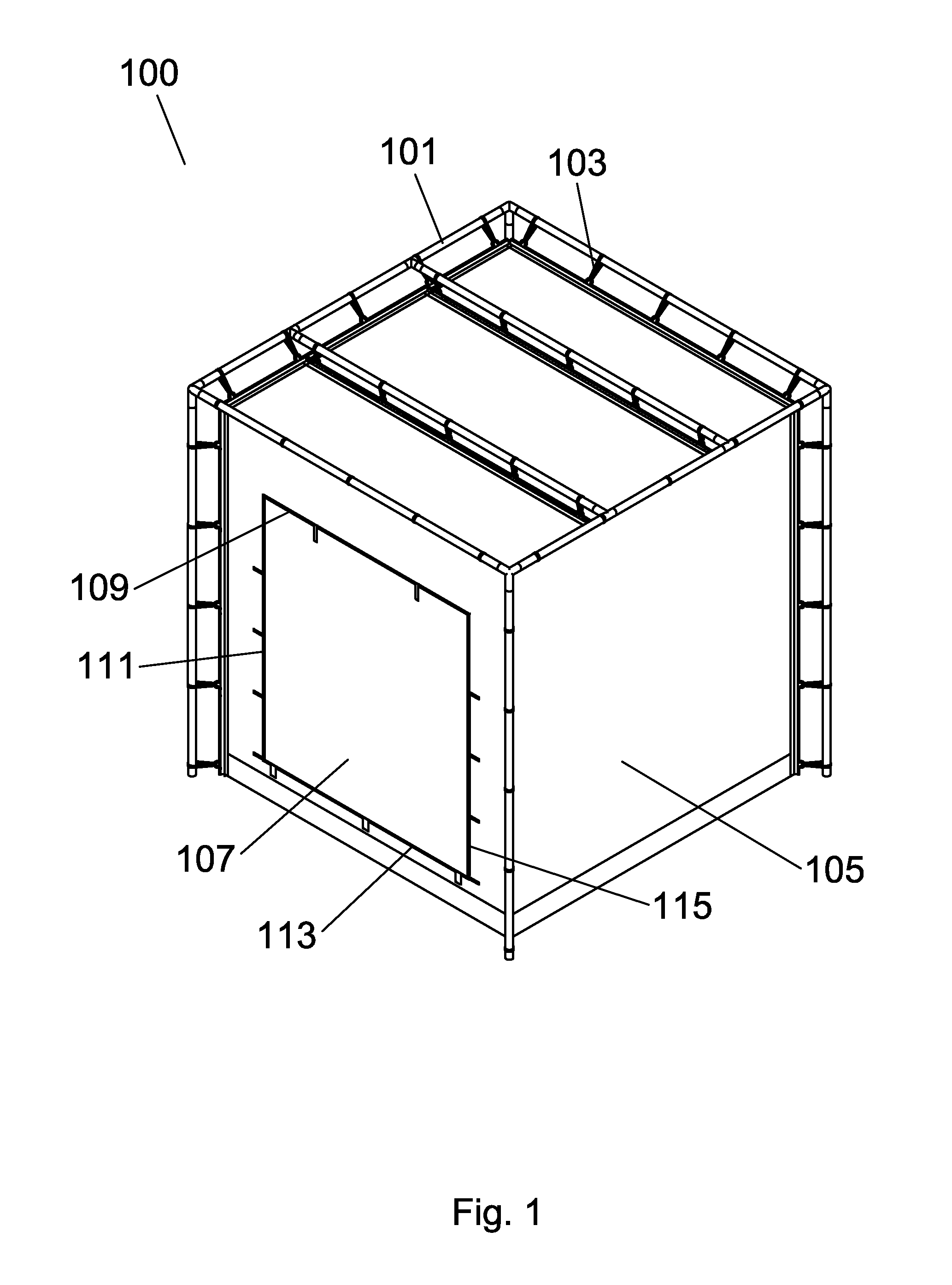
[0025]FIG. 1 is a perspective view of an electromagnetically shielded enclosure 100 and entry seal. The electromagneti...


PUM


Abstract

An electromagnetically shielded enclosure that is portable and lightweight that can be used for applications such as testing and security. The electromagnetically shielded enclosure has a novel entry seal that eliminates the electromagnetic leakage that is common around the entry areas of such enclosures. The entry seal has an outer door with a perimeter magnetic material, an outer door magnetic closure that aligns with the outer door perimeter magnetic material, an inner door with a perimeter magnetic material, and an inner door magnetic closure that aligns with the inner door perimeter magnetic material.

Description

CROSS REFERENCE TO RELATED PATENT APPLICATIONS[0001]This application claims priority to U.S. Patent Application Ser. No. 61 / 171,133 filed Apr. 21, 2009 entitled “Electromagnetically Shielded Enclosure And Entry Seal” by Gary W. Winch of Naples, N.Y.BACKGROUND OF THE INVENTION[0002]1. Field of the Invention[0003]This invention relates generally to electromagnetic shielding, and more specifically to an electromagnetically shielded enclosure having a novel entry seal.[0004]2. Description of Related Art[0005]As the proliferation of radiofrequency generating devices continues at a rapid pace, there is an ongoing and growing need to shield from unwanted electromagnetic radiation for various purposes. For example, certain electronic equipment requires an electromagnetically “quiet” environment to function properly. Such equipment includes, for example, some medical diagnostic and imaging equipment. In addition, testing of electronic equipment often requires a similar electromagnetically “q...

Claims


Application Information

Patent Timeline
IPC IPC(8): H05K9/00
CPCH05K9/0001G01R29/0821
Inventor WINCH, GARY WILLIAM
Owner SELECT FABTORS
Why Eureka
Try Eureka