Hydraulic booster and hydraulic brake system using the same

a brake system and hydraulic booster technology, applied in the direction of brake action initiation, brake system, vehicle components, etc., can solve the problems of abnormal rise in the master cylinder pressure and the boost pressure, and the inability to use the negative pressure generated in the engine to produce such a assisting force, so as to prevent excessive pressure rise, and prevent the effect of reducing durability

Active Publication Date: 2013-09-17
ADVICS CO LTD
View PDF15 Cites 4 Cited by
  • Summary
  • Abstract
  • Description
  • Claims
  • Application Information

AI Technical Summary

Benefits of technology

[0017](1) A hydraulic booster for use in a hydraulic brake system, including an auxiliary hydraulic pressure source including a power pump and a pressure accumulator, a pressure regulator including a spool valve and configured to adjust hydraulic pressure supplied from the auxiliary hydraulic pressure source to a value corresponding to an operating amount of a brake operating member by displacement of the spool valve and to introduce the thus adjusted hydraulic pressure into a boost chamber, and a boost piston for producing an assisting force under the hydraulic pressure introduced into the boost chamber, thereby actuating a master piston of a master cylinder with an assisted force, wherein the hydraulic booster further comprises at least one hydraulic line which bypasses the pressure regulator and through which one of the boost chamber and a pressure chamber of the master cylinder is connected to one of the auxiliary hydraulic pressure source and an atmospheric pressure reservoir, and at least one check valve provided in the hydraulic line and configured to allow only a discharge of hydraulic pressure from the one of the boost chamber and the pressure chamber of the master cylinder to the one of the auxiliary hydraulic pressure source and the atmospheric pressure reservoir.
[0034]In the hydraulic booster and the hydraulic brake system according to the present invention, when the piston of the master cylinder and the boost piston are pushed back due to the pump back flow, the check valve opens under the increased pressure in the boost chamber, releasing the pressure in the boost chamber into the auxiliary hydraulic pressure source or into the atmospheric pressure reservoir. This prevents an excessive rise in pressure in the boost chamber, which in turn prevents reduced durability and possible breakage of the master cylinder and the hydraulic booster due to excessive pressure.
[0034]In the hydraulic booster and the hydraulic brake system according to the present invention, when the piston of the master cylinder and the boost piston are pushed back due to the pump back flow, the check valve opens under the increased pressure in the boost chamber, releasing the pressure in the boost chamber into the auxiliary hydraulic pressure source or into the atmospheric pressure reservoir. This prevents an excessive rise in pressure in the boost chamber, which in turn prevents reduced durability and possible breakage of the master cylinder and the hydraulic booster due to excessive pressure.
[0036]By adding the sticking preventive mechanism, it is possible to minimize the possibility of the check valve getting stuck, ensuring fail-safe operation.
[0028](4) A hydraulic brake system including one of the above-described boosters (1) to (3), a brake operating member configured to apply a brake operating force to the hydraulic booster, a master cylinder including a master piston configured to be actuated while receiving an assisting force from the hydraulic booster, thus producing a hydraulic pressure in the master cylinder, wheel cylinders configured to produce a braking force under the hydraulic pressure supplied from the master cylinder,
[0039]Preferably, the controller is used together with the check valve such that in an emergency where the check valve gets stuck, the controller stops the pump from drawing brake fluid. But this controller may used alone, i.e. without providing the check valve, such that the controller stops the pump from drawing brake fluid whenever necessary to prevent reduction in durability of the fluid seals and breakage of the master cylinder and the hydraulic booster due to pump back flow.

Problems solved by technology

But it is impossible use a negative pressure generated in an engine to produce such an assisting force if the vehicle is a hybrid electric vehicle (HEV), an electric vehicle (EV) or a Valvematic vehicle, in which the valve lifts of the intake valves are continuously variable such that the intake valves serve as throttle valves.
But if such a hydraulic booster is used instead of a vacuum booster, the pump back flow could cause an abnormal rise in the master cylinder pressure and the boost pressure.

Method used


Image

  • Hydraulic booster and hydraulic brake system using the same
  • Hydraulic booster and hydraulic brake system using the same
  • Hydraulic booster and hydraulic brake system using the same

Examples


Embodiment Construction

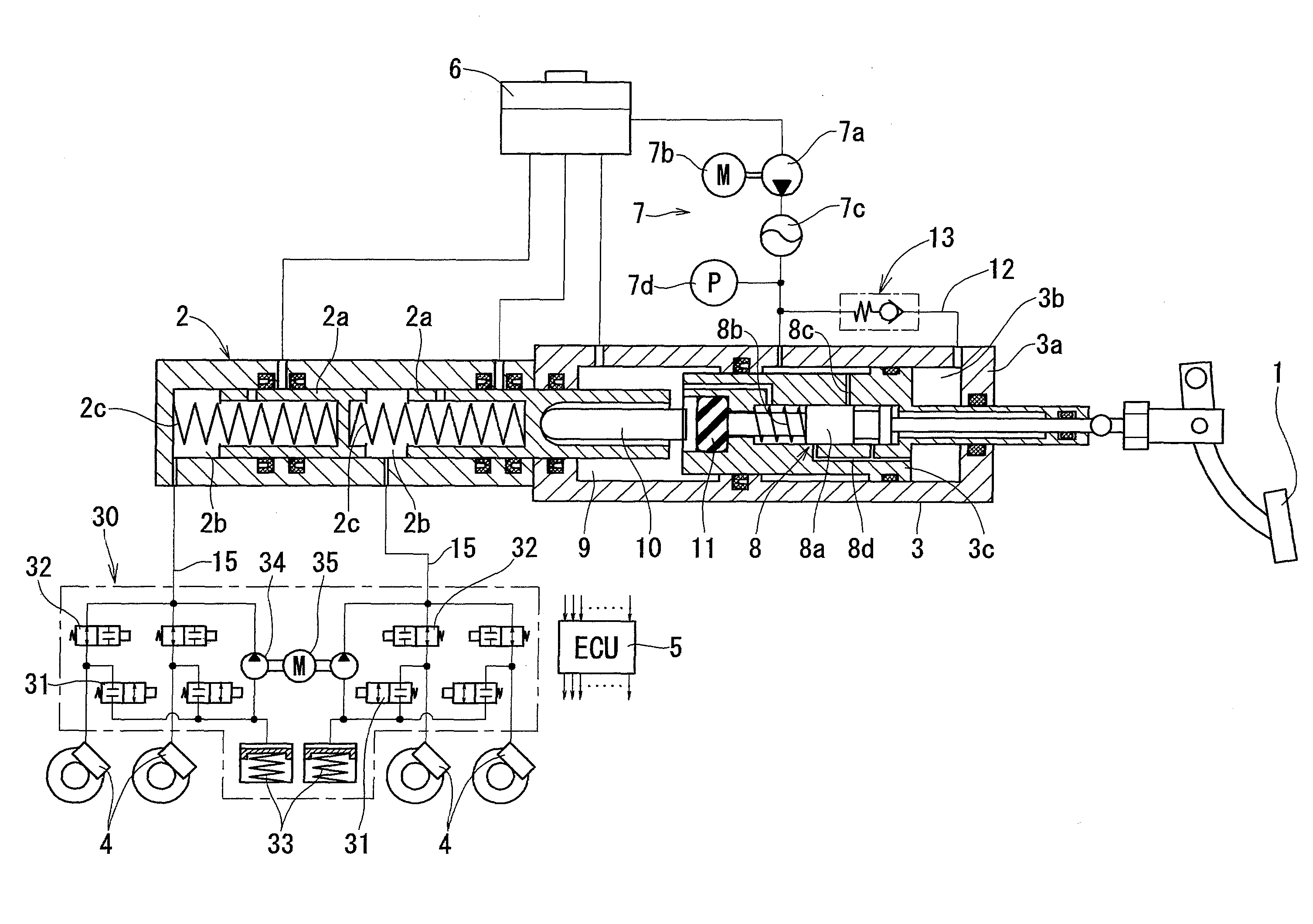
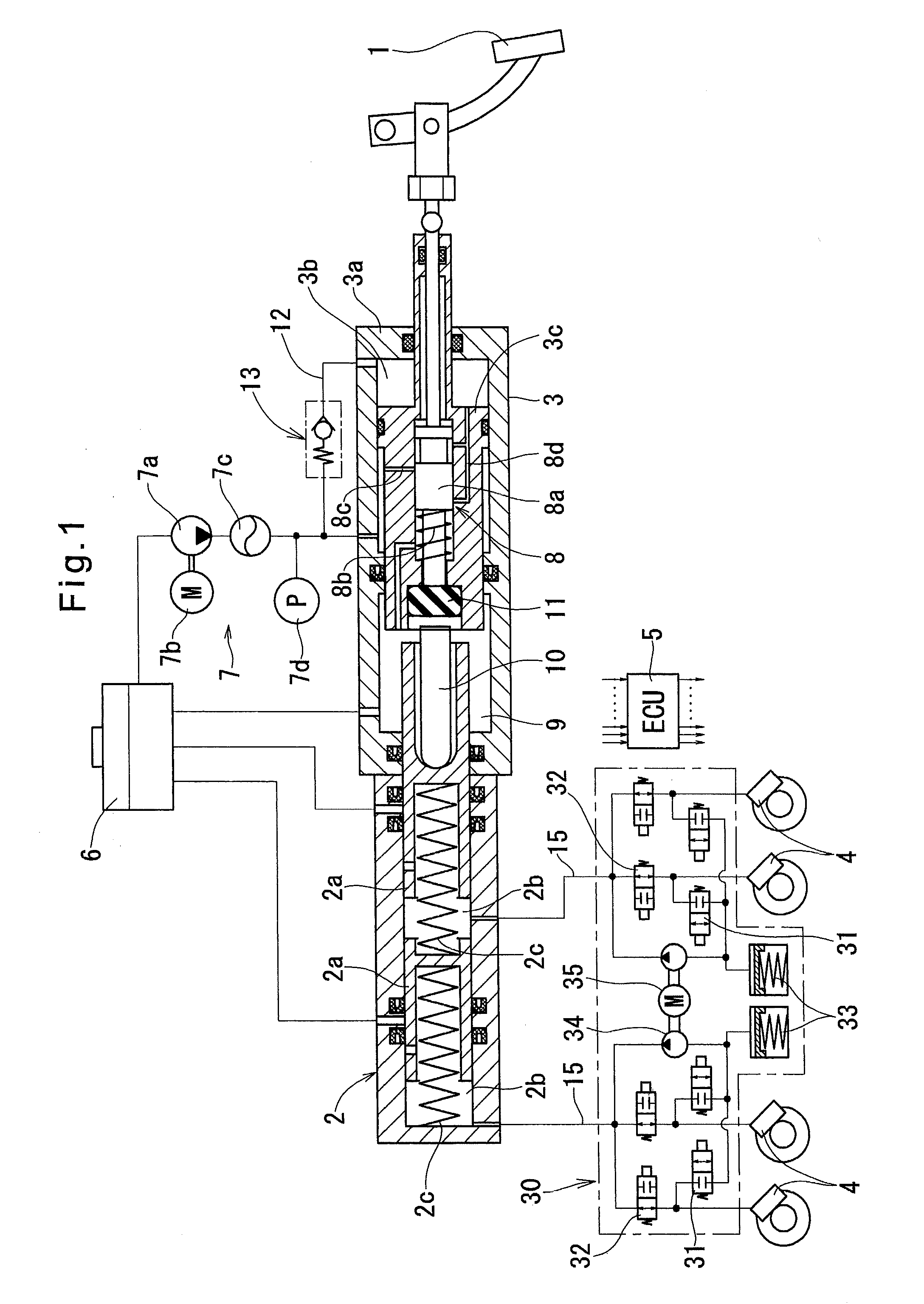
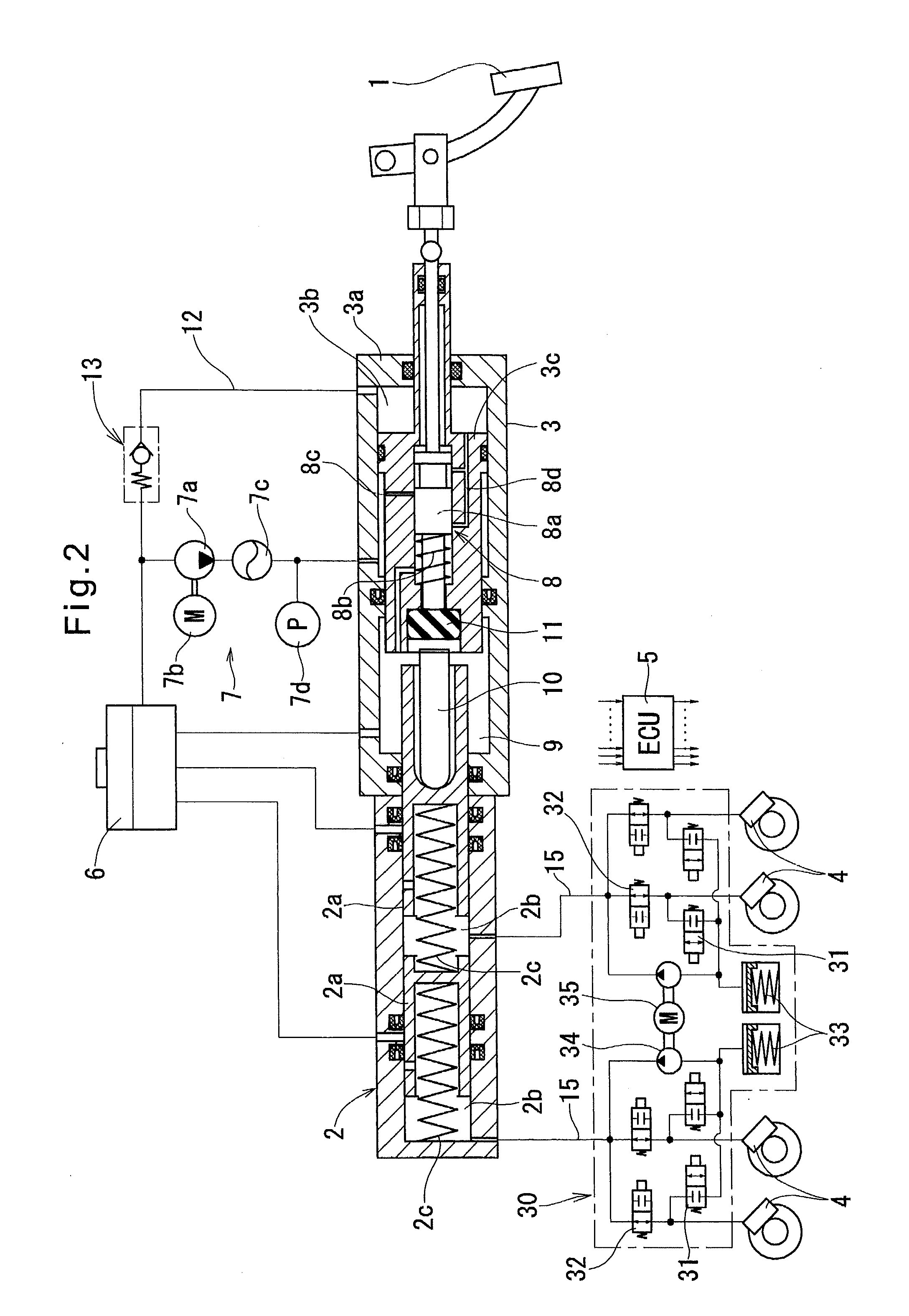
[0057]Referring to FIGS. 1 to 17, description is made of the embodiments of the hydraulic booster according to the present invention and the hydraulic brake system including this hydraulic pressure booster.

[0058]The hydraulic brake system shown in FIG. 1 (first embodiment) includes a brake operating member 1 (which is a brake pedal in the embodiment shown), a master cylinder 2, a hydraulic booster 3, wheel cylinders 4 which generate braking force based on hydraulic pressure supplied from the master cylinder 2, a circulation type pressure control unit 30, and an electronic control unit 5. The brake system further includes an atmospheric pressure reservoir 6 as a replenishing fluid source. The brake system further includes sensors which supply information necessary for the electronic control unit 5 to determine whether to increase or reduce the pressures of the respective wheel cylinders 4. But these sensors are not shown.

[0059]The master cylinder 2 shown is a known tandem master cyli...


PUM


Abstract

A hydraulic brake system is proposed which includes a hydraulic booster for boosting brake operation, and a circulation type pressure control unit. The hydraulic brake system further includes a hydraulic booster including an auxiliary hydraulic pressure source, a pressure regulator for adjusting the hydraulic pressure supplied therefrom to a value corresponding to an operating amount of a brake operating member and introducing the thus adjusted hydraulic pressure into a boost chamber, and a boost piston for actuating a master piston with a force boosted by an assisting force generated by the hydraulic pressure introduced into the boost chamber. The hydraulic booster further includes a hydraulic line bypassing the pressure regulator and extending from the boost chamber to the auxiliary hydraulic pressure, and a check valve provided in the hydraulic line and configured to allow only a discharge of hydraulic pressure from the boost chamber into the auxiliary hydraulic pressure source.

Description

TECHNICAL FIELD[0001]This invention relates to a hydraulic booster which generates an assisting force corresponding to an operating amount of a brake operating member based on hydraulic pressure supplied from an auxiliary hydraulic pressure source, and applies the assisted braking force to a master cylinder, and a hydraulic brake system including such a hydraulic booster.BACKGROUND ART[0002]The below-identified Patent document 1 discloses a hydraulic booster including an auxiliary hydraulic pressure source having a power pump and a pressure accumulator, and a pressure regulator including a spool valve and configured to adjust the hydraulic pressure supplied from the auxiliary hydraulic pressure source to a value corresponding to the operating amount of a brake operating member, and to introduce the thus adjusted hydraulic pressure into a boost chamber as an assisting force, in which an assisted force (sum of the brake operating force applied by a driver of the vehicle and the above ...

Claims


Application Information

Patent Timeline
Patent Type & Authority Patents(United States)
IPC IPC(8): B60T8/44
CPCB60T8/4275B60T8/441B60T13/66B60T8/17B60T13/145B60T13/147B60T7/042B60T13/146B60T13/662B60T13/686
Inventor HONDA, TETSUYAYAMAMOTO, HIDEKINOHIRA, SHIGEMITSUMIYATA, YOSHIHIRO
Owner ADVICS CO LTD
Why Eureka
Try Eureka